

(9) to identify the overall loads the load forces of the cage structure and the load
forces of the entire net harness (including the mesh size) were superposed.
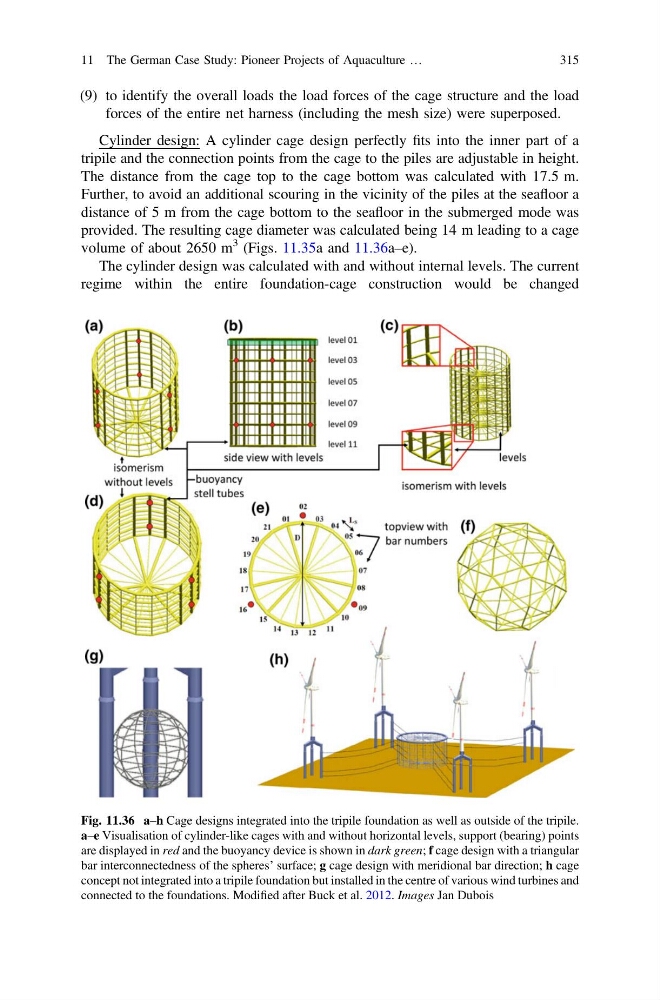
Cylinder design: A cylinder cage design perfectly fits into the inner part of a
tripile and the connection points from the cage to the piles are adjustable in height.
The distance from the cage top to the cage bottom was calculated with 17.5 m.
Further, to avoid an additional scouring in the vicinity of the piles at the seafloor a
distance of 5 m from the cage bottom to the seafloor in the submerged mode was
provided. The resulting cage diameter was calculated being 14 m leading to a cage
volume of about 2650 m
3 (Figs. 11.35a and 11.36a–e).
The cylinder design was calculated with and without internal levels. The current
regime within the entire foundation-cage construction would be changed
Fig. 11.36 a–h Cage designs integrated into the tripile foundation as well as outside of the tripile.
a–e Visualisation of cylinder-like cages with and without horizontal levels, support (bearing) points
are displayed in red and the buoyancy device is shown in dark green; f cage design with a triangular
bar interconnectedness of the spheres’ surface; g cage design with meridional bar direction; h cage
concept not integrated into a tripile foundation but installed in the centre of various wind turbines and
connected to the foundations. Modified after Buck et al. 2012. Images Jan Dubois
11 The German Case Study: Pioneer Projects of Aquaculture …
315
forces of the entire net harness (including the mesh size) were superposed.
Cylinder design: A cylinder cage design perfectly fits into the inner part of a
tripile and the connection points from the cage to the piles are adjustable in height.
The distance from the cage top to the cage bottom was calculated with 17.5 m.
Further, to avoid an additional scouring in the vicinity of the piles at the seafloor a
distance of 5 m from the cage bottom to the seafloor in the submerged mode was
provided. The resulting cage diameter was calculated being 14 m leading to a cage
volume of about 2650 m
3 (Figs. 11.35a and 11.36a–e).
The cylinder design was calculated with and without internal levels. The current
regime within the entire foundation-cage construction would be changed
Fig. 11.36 a–h Cage designs integrated into the tripile foundation as well as outside of the tripile.
a–e Visualisation of cylinder-like cages with and without horizontal levels, support (bearing) points
are displayed in red and the buoyancy device is shown in dark green; f cage design with a triangular
bar interconnectedness of the spheres’ surface; g cage design with meridional bar direction; h cage
concept not integrated into a tripile foundation but installed in the centre of various wind turbines and
connected to the foundations. Modified after Buck et al. 2012. Images Jan Dubois
11 The German Case Study: Pioneer Projects of Aquaculture …
315