

flume and wave tank results to optimise the final cage design. However, the
evaluation of the potential impact of the additional loads due to the attached cage
structures on the dimensioning of the support structure was not focused on. The
basic data of the test site at “Veja Mate” are shown in the following table
(Table 11.2).
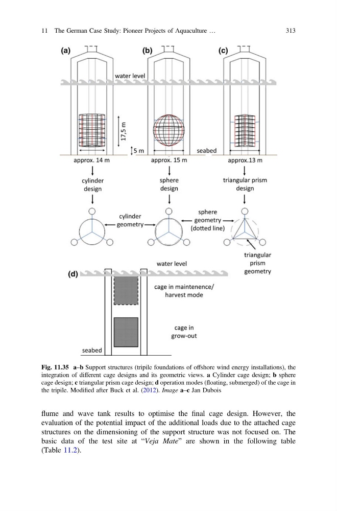
Fig. 11.35 a–b Support structures (tripile foundations of offshore wind energy installations), the
integration of different cage designs and its geometric views. a Cylinder cage design; b sphere
cage design; c triangular prism cage design; d operation modes (floating, submerged) of the cage in
the tripile. Modified after Buck et al. (2012). Image a–c Jan Dubois
11 The German Case Study: Pioneer Projects of Aquaculture …
313
evaluation of the potential impact of the additional loads due to the attached cage
structures on the dimensioning of the support structure was not focused on. The
basic data of the test site at “Veja Mate” are shown in the following table
(Table 11.2).
Fig. 11.35 a–b Support structures (tripile foundations of offshore wind energy installations), the
integration of different cage designs and its geometric views. a Cylinder cage design; b sphere
cage design; c triangular prism cage design; d operation modes (floating, submerged) of the cage in
the tripile. Modified after Buck et al. (2012). Image a–c Jan Dubois
11 The German Case Study: Pioneer Projects of Aquaculture …
313