

calculated similar to the collector (Fig. 11.31b). As the vertical forces were caused
by the mass of the collector and the buoyancy the mass force was defined as
F m ¼ m Á g
ð11:6Þ
with
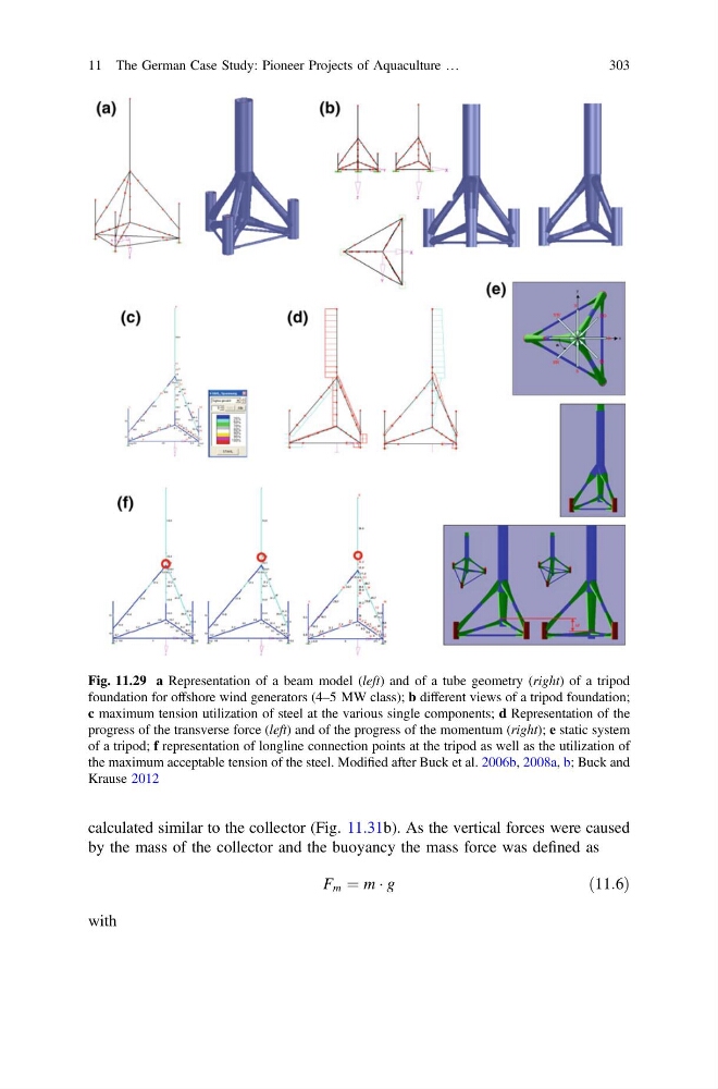
Fig. 11.29 a Representation of a beam model (left) and of a tube geometry (right) of a tripod
foundation for offshore wind generators (4–5 MW class); b different views of a tripod foundation;
c maximum tension utilization of steel at the various single components; d Representation of the
progress of the transverse force (left) and of the progress of the momentum (right); e static system
of a tripod; f representation of longline connection points at the tripod as well as the utilization of
the maximum acceptable tension of the steel. Modified after Buck et al. 2006b, 2008a, b; Buck and
Krause 2012
11 The German Case Study: Pioneer Projects of Aquaculture …
303
by the mass of the collector and the buoyancy the mass force was defined as
F m ¼ m Á g
ð11:6Þ
with
Fig. 11.29 a Representation of a beam model (left) and of a tube geometry (right) of a tripod
foundation for offshore wind generators (4–5 MW class); b different views of a tripod foundation;
c maximum tension utilization of steel at the various single components; d Representation of the
progress of the transverse force (left) and of the progress of the momentum (right); e static system
of a tripod; f representation of longline connection points at the tripod as well as the utilization of
the maximum acceptable tension of the steel. Modified after Buck et al. 2006b, 2008a, b; Buck and
Krause 2012
11 The German Case Study: Pioneer Projects of Aquaculture …
303