

has a main joint, which is the technical limit for the depth of the connection point.
This is located about 5 m below the water line (Fig. 11.30).
11.4.1.6 Additional Forces Measurement
To estimate the maximal forces in order to qualify the load sensor class some
previous calculations were conducted. Figure 11.31a shows a schematic depiction
of a single collector load system. Further, the load forces of the attached buoys were
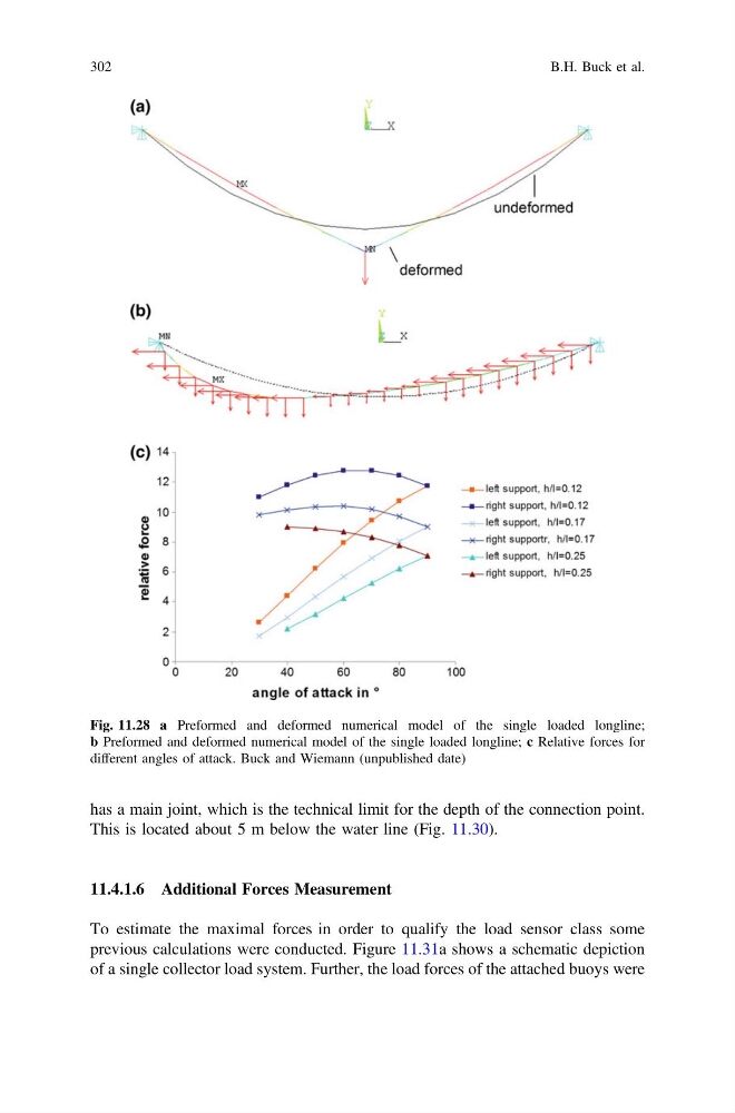
Fig. 11.28 a Preformed and deformed numerical model of the single loaded longline;
b Preformed and deformed numerical model of the single loaded longline; c Relative forces for
different angles of attack. Buck and Wiemann (unpublished date)
302
B.H. Buck et al.
This is located about 5 m below the water line (Fig. 11.30).
11.4.1.6 Additional Forces Measurement
To estimate the maximal forces in order to qualify the load sensor class some
previous calculations were conducted. Figure 11.31a shows a schematic depiction
of a single collector load system. Further, the load forces of the attached buoys were
Fig. 11.28 a Preformed and deformed numerical model of the single loaded longline;
b Preformed and deformed numerical model of the single loaded longline; c Relative forces for
different angles of attack. Buck and Wiemann (unpublished date)
302
B.H. Buck et al.