

3.2 Digital Implementation
49
[0] [1]
[2][3]
[5]
[6]
Clock generator switch box
ADC clk
[4]
Clock configuration pins:
320
20
1 1 0
1 1 0 0
320
10
1 1 1
1 1 1 0
320
5
1 0 1
1 1 1 1
160
20
0 1 0
0 1 0 0
160
10
0 1 1
0 1 1 0
160
5
1 0 0
0 1 1 1
80
10
0 0 1
0 0 1 0
80
5
0 0 0
0 0 1 1
Serial clk
÷2
÷2
÷2
÷2
1
0
1
0
÷2
÷2 1
0
1
0
ADC delay
1
0
÷2
1
0
clk
gating
1
0
1
0
clk
gating
clk
gating
÷2
÷2 1
0
÷2
1
0
320/160/80 MHz
40 MHz
BX clk
ADC analogue clk*
*To Analogue Domain (ADC)
BX clk in
Serial clk in
ADC SAR clk*
Serial clk un-gated
ADC clk un-gated
ADC clk
Serial clk
Serial clk div 2
5/10/20 MHz
ADC clk in
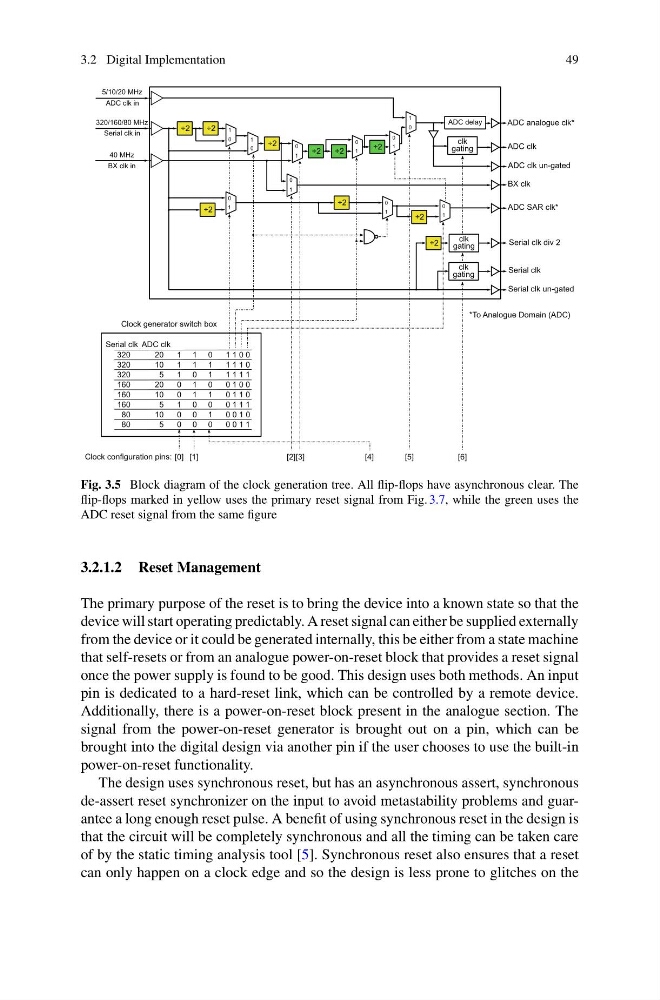
Fig. 3.5 Block diagram of the clock generation tree. All flip-flops have asynchronous clear. The
flip-flops marked in yellow uses the primary reset signal from Fig. 3.7, while the green uses the
ADC reset signal from the same figure
3.2.1.2 Reset Management
The primary purpose of the reset is to bring the device into a known state so that the
device will start operating predictably. A reset signal can either be supplied externally
from the device or it could be generated internally, this be either from a state machine
that self-resets or from an analogue power-on-reset block that provides a reset signal
once the power supply is found to be good. This design uses both methods. An input
pin is dedicated to a hard-reset link, which can be controlled by a remote device.
Additionally, there is a power-on-reset block present in the analogue section. The
signal from the power-on-reset generator is brought out on a pin, which can be
brought into the digital design via another pin if the user chooses to use the built-in
power-on-reset functionality.
The design uses synchronous reset, but has an asynchronous assert, synchronous
de-assert reset synchronizer on the input to avoid metastability problems and guarantee a long enough reset pulse. A benefit of using synchronous reset in the design is
that the circuit will be completely synchronous and all the timing can be taken care
of by the static timing analysis tool [5]. Synchronous reset also ensures that a reset
can only happen on a clock edge and so the design is less prone to glitches on the
49
[0] [1]
[2][3]
[5]
[6]
Clock generator switch box
ADC clk
[4]
Clock configuration pins:
320
20
1 1 0
1 1 0 0
320
10
1 1 1
1 1 1 0
320
5
1 0 1
1 1 1 1
160
20
0 1 0
0 1 0 0
160
10
0 1 1
0 1 1 0
160
5
1 0 0
0 1 1 1
80
10
0 0 1
0 0 1 0
80
5
0 0 0
0 0 1 1
Serial clk
÷2
÷2
÷2
÷2
1
0
1
0
÷2
÷2 1
0
1
0
ADC delay
1
0
÷2
1
0
clk
gating
1
0
1
0
clk
gating
clk
gating
÷2
÷2 1
0
÷2
1
0
320/160/80 MHz
40 MHz
BX clk
ADC analogue clk*
*To Analogue Domain (ADC)
BX clk in
Serial clk in
ADC SAR clk*
Serial clk un-gated
ADC clk un-gated
ADC clk
Serial clk
Serial clk div 2
5/10/20 MHz
ADC clk in
Fig. 3.5 Block diagram of the clock generation tree. All flip-flops have asynchronous clear. The
flip-flops marked in yellow uses the primary reset signal from Fig. 3.7, while the green uses the
ADC reset signal from the same figure
3.2.1.2 Reset Management
The primary purpose of the reset is to bring the device into a known state so that the
device will start operating predictably. A reset signal can either be supplied externally
from the device or it could be generated internally, this be either from a state machine
that self-resets or from an analogue power-on-reset block that provides a reset signal
once the power supply is found to be good. This design uses both methods. An input
pin is dedicated to a hard-reset link, which can be controlled by a remote device.
Additionally, there is a power-on-reset block present in the analogue section. The
signal from the power-on-reset generator is brought out on a pin, which can be
brought into the digital design via another pin if the user chooses to use the built-in
power-on-reset functionality.
The design uses synchronous reset, but has an asynchronous assert, synchronous
de-assert reset synchronizer on the input to avoid metastability problems and guarantee a long enough reset pulse. A benefit of using synchronous reset in the design is
that the circuit will be completely synchronous and all the timing can be taken care
of by the static timing analysis tool [5]. Synchronous reset also ensures that a reset
can only happen on a clock edge and so the design is less prone to glitches on the