

44
3 SAMPA Chip Implementation
SAR
Comp
2C u
4C u
16C u
C u
2C u
4C u
8C u
REF+
V REFV REFV REF+
V IN+
V INCLK C
32C u
32C u
16C u
64C u
C u
valid
V DACN
V DACP
64C u
Sample clock
SAR clock
Data [9:0]
C u
2C u
4C u
C u
C u
2C u
4C u
8C u
C u
V
C u = 26 fF (4 μm x 4 μm)
C p
C p
sample
sample
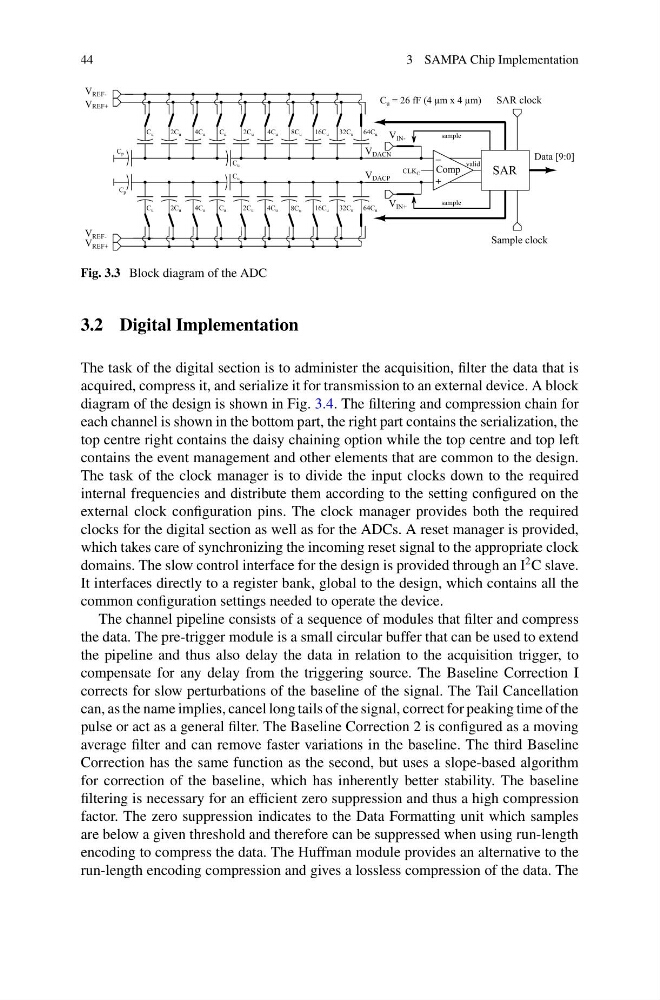
Fig. 3.3 Block diagram of the ADC
3.2 Digital Implementation
The task of the digital section is to administer the acquisition, filter the data that is
acquired, compress it, and serialize it for transmission to an external device. A block
diagram of the design is shown in Fig. 3.4. The filtering and compression chain for
each channel is shown in the bottom part, the right part contains the serialization, the
top centre right contains the daisy chaining option while the top centre and top left
contains the event management and other elements that are common to the design.
The task of the clock manager is to divide the input clocks down to the required
internal frequencies and distribute them according to the setting configured on the
external clock configuration pins. The clock manager provides both the required
clocks for the digital section as well as for the ADCs. A reset manager is provided,
which takes care of synchronizing the incoming reset signal to the appropriate clock
domains. The slow control interface for the design is provided through an I
2 C slave.
It interfaces directly to a register bank, global to the design, which contains all the
common configuration settings needed to operate the device.
The channel pipeline consists of a sequence of modules that filter and compress
the data. The pre-trigger module is a small circular buffer that can be used to extend
the pipeline and thus also delay the data in relation to the acquisition trigger, to
compensate for any delay from the triggering source. The Baseline Correction I
corrects for slow perturbations of the baseline of the signal. The Tail Cancellation
can, as the name implies, cancel long tails of the signal, correct for peaking time of the
pulse or act as a general filter. The Baseline Correction 2 is configured as a moving
average filter and can remove faster variations in the baseline. The third Baseline
Correction has the same function as the second, but uses a slope-based algorithm
for correction of the baseline, which has inherently better stability. The baseline
filtering is necessary for an efficient zero suppression and thus a high compression
factor. The zero suppression indicates to the Data Formatting unit which samples
are below a given threshold and therefore can be suppressed when using run-length
encoding to compress the data. The Huffman module provides an alternative to the
run-length encoding compression and gives a lossless compression of the data. The
3 SAMPA Chip Implementation
SAR
Comp
2C u
4C u
16C u
C u
2C u
4C u
8C u
REF+
V REFV REFV REF+
V IN+
V INCLK C
32C u
32C u
16C u
64C u
C u
valid
V DACN
V DACP
64C u
Sample clock
SAR clock
Data [9:0]
C u
2C u
4C u
C u
C u
2C u
4C u
8C u
C u
V
C u = 26 fF (4 μm x 4 μm)
C p
C p
sample
sample
Fig. 3.3 Block diagram of the ADC
3.2 Digital Implementation
The task of the digital section is to administer the acquisition, filter the data that is
acquired, compress it, and serialize it for transmission to an external device. A block
diagram of the design is shown in Fig. 3.4. The filtering and compression chain for
each channel is shown in the bottom part, the right part contains the serialization, the
top centre right contains the daisy chaining option while the top centre and top left
contains the event management and other elements that are common to the design.
The task of the clock manager is to divide the input clocks down to the required
internal frequencies and distribute them according to the setting configured on the
external clock configuration pins. The clock manager provides both the required
clocks for the digital section as well as for the ADCs. A reset manager is provided,
which takes care of synchronizing the incoming reset signal to the appropriate clock
domains. The slow control interface for the design is provided through an I
2 C slave.
It interfaces directly to a register bank, global to the design, which contains all the
common configuration settings needed to operate the device.
The channel pipeline consists of a sequence of modules that filter and compress
the data. The pre-trigger module is a small circular buffer that can be used to extend
the pipeline and thus also delay the data in relation to the acquisition trigger, to
compensate for any delay from the triggering source. The Baseline Correction I
corrects for slow perturbations of the baseline of the signal. The Tail Cancellation
can, as the name implies, cancel long tails of the signal, correct for peaking time of the
pulse or act as a general filter. The Baseline Correction 2 is configured as a moving
average filter and can remove faster variations in the baseline. The third Baseline
Correction has the same function as the second, but uses a slope-based algorithm
for correction of the baseline, which has inherently better stability. The baseline
filtering is necessary for an efficient zero suppression and thus a high compression
factor. The zero suppression indicates to the Data Formatting unit which samples
are below a given threshold and therefore can be suppressed when using run-length
encoding to compress the data. The Huffman module provides an alternative to the
run-length encoding compression and gives a lossless compression of the data. The