

Appendix B: Registers
149
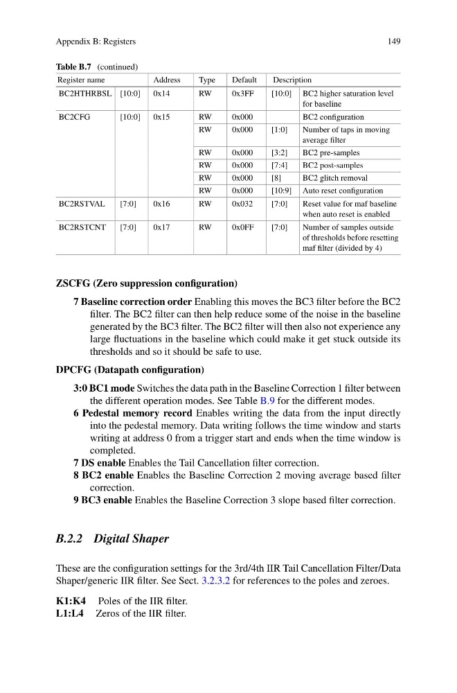
Table B.7 (continued)
Register name
Address
Type
Default
Description
BC2HTHRBSL [10:0]
0x14
RW
0x3FF
[10:0] BC2 higher saturation level
for baseline
BC2CFG
[10:0]
0x15
RW
0x000
BC2 configuration
RW
0x000
[1:0]
Number of taps in moving
average filter
RW
0x000
[3:2]
BC2 pre-samples
RW
0x000
[7:4]
BC2 post-samples
RW
0x000
[8]
BC2 glitch removal
RW
0x000
[10:9] Auto reset configuration
BC2RSTVAL
[7:0]
0x16
RW
0x032
[7:0]
Reset value for maf baseline
when auto reset is enabled
BC2RSTCNT
[7:0]
0x17
RW
0x0FF
[7:0]
Number of samples outside
of thresholds before resetting
maf filter (divided by 4)
ZSCFG (Zero suppression configuration)
7 Baseline correction order Enabling this moves the BC3 filter before the BC2
filter. The BC2 filter can then help reduce some of the noise in the baseline
generated by the BC3 filter. The BC2 filter will then also not experience any
large fluctuations in the baseline which could make it get stuck outside its
thresholds and so it should be safe to use.
DPCFG (Datapath configuration)
3:0 BC1 mode Switches the data path in the Baseline Correction 1 filter between
the different operation modes. See Table B.9 for the different modes.
6 Pedestal memory record Enables writing the data from the input directly
into the pedestal memory. Data writing follows the time window and starts
writing at address 0 from a trigger start and ends when the time window is
completed.
7 DS enable Enables the Tail Cancellation filter correction.
8 BC2 enable Enables the Baseline Correction 2 moving average based filter
correction.
9 BC3 enable Enables the Baseline Correction 3 slope based filter correction.
B.2.2 Digital Shaper
These are the configuration settings for the 3rd/4th IIR Tail Cancellation Filter/Data
Shaper/generic IIR filter. See Sect. 3.2.3.2 for references to the poles and zeroes.
K1:K4 Poles of the IIR filter.
L1:L4 Zeros of the IIR filter.
149
Table B.7 (continued)
Register name
Address
Type
Default
Description
BC2HTHRBSL [10:0]
0x14
RW
0x3FF
[10:0] BC2 higher saturation level
for baseline
BC2CFG
[10:0]
0x15
RW
0x000
BC2 configuration
RW
0x000
[1:0]
Number of taps in moving
average filter
RW
0x000
[3:2]
BC2 pre-samples
RW
0x000
[7:4]
BC2 post-samples
RW
0x000
[8]
BC2 glitch removal
RW
0x000
[10:9] Auto reset configuration
BC2RSTVAL
[7:0]
0x16
RW
0x032
[7:0]
Reset value for maf baseline
when auto reset is enabled
BC2RSTCNT
[7:0]
0x17
RW
0x0FF
[7:0]
Number of samples outside
of thresholds before resetting
maf filter (divided by 4)
ZSCFG (Zero suppression configuration)
7 Baseline correction order Enabling this moves the BC3 filter before the BC2
filter. The BC2 filter can then help reduce some of the noise in the baseline
generated by the BC3 filter. The BC2 filter will then also not experience any
large fluctuations in the baseline which could make it get stuck outside its
thresholds and so it should be safe to use.
DPCFG (Datapath configuration)
3:0 BC1 mode Switches the data path in the Baseline Correction 1 filter between
the different operation modes. See Table B.9 for the different modes.
6 Pedestal memory record Enables writing the data from the input directly
into the pedestal memory. Data writing follows the time window and starts
writing at address 0 from a trigger start and ends when the time window is
completed.
7 DS enable Enables the Tail Cancellation filter correction.
8 BC2 enable Enables the Baseline Correction 2 moving average based filter
correction.
9 BC3 enable Enables the Baseline Correction 3 slope based filter correction.
B.2.2 Digital Shaper
These are the configuration settings for the 3rd/4th IIR Tail Cancellation Filter/Data
Shaper/generic IIR filter. See Sect. 3.2.3.2 for references to the poles and zeroes.
K1:K4 Poles of the IIR filter.
L1:L4 Zeros of the IIR filter.