

150
Appendix B: Registers
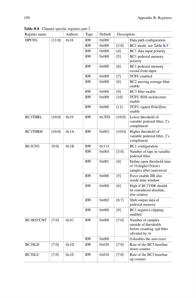
Table B.8 Channel specific registers part 2
Register name
Address
Type
Default
Description
DPCFG
[11:0] 0x18
RW
0x000
Data path configuration
RW
0x000
[3:0]
BC1 mode, see Table B.9
RW
0x000
[4]
BC1 data input polarity
RW
0x000
[5]
BC1 pedestal memory
polarity
RW
0x000
[6]
BC1 pedestal memory
record from input
RW
0x000
[7]
TCFU enabled
RW
0x000
[8]
BC2 moving average filter
enable
RW
0x000
[9]
BC3 filter enable
RW
0x000
[10]
TCFU SOS architecture
enable
RW
0x000
[11]
TCFU signed Pole/Zero
enable
BC1THRL
[10:0] 0x19
RW
0x7FD
[10:0] Lower threshold of
variable pedestal filter, 2’s
compliment
BC1THRH
[10:0] 0x1A
RW
0x003
[10:0] Higher threshold of
variable pedestal filter, 2’s
compliment
BC1CFG
[9:0]
0x1B
RW
0x114
BC1 configuration
RW
0x004
[3:0]
Number of taps in variable
pedestal filter
RW
0x001
[4]
Define open threshold time
of 31(high)/15(low)
samples after (auto)reset
RW
0x000
[5]
Force enable IIR also
inside time window
RW
0x000
[6]
High if BC1THR should
be considered absolute,
else relative
RW
0x002
[8:7]
Shift output data of
pedestal memory
RW
0x000
[9]
BC1 negative clipping
enabled
BC1RSTCNT [7:0]
0x1C
RW
0x000
[7:0]
Number of samples
outside of thresholds
before resetting vpd filter
(divided by 4)
RW
0x000
0 disables the auto reset
BC3SLD
[7:0]
0x1D
RW
0x020
[7:0]
Rate of the BC3 baseline
down counter
BC3SLU
[7:0]
0x1E
RW
0x010
[7:0]
Rate of the BC3 baseline
up counter
Appendix B: Registers
Table B.8 Channel specific registers part 2
Register name
Address
Type
Default
Description
DPCFG
[11:0] 0x18
RW
0x000
Data path configuration
RW
0x000
[3:0]
BC1 mode, see Table B.9
RW
0x000
[4]
BC1 data input polarity
RW
0x000
[5]
BC1 pedestal memory
polarity
RW
0x000
[6]
BC1 pedestal memory
record from input
RW
0x000
[7]
TCFU enabled
RW
0x000
[8]
BC2 moving average filter
enable
RW
0x000
[9]
BC3 filter enable
RW
0x000
[10]
TCFU SOS architecture
enable
RW
0x000
[11]
TCFU signed Pole/Zero
enable
BC1THRL
[10:0] 0x19
RW
0x7FD
[10:0] Lower threshold of
variable pedestal filter, 2’s
compliment
BC1THRH
[10:0] 0x1A
RW
0x003
[10:0] Higher threshold of
variable pedestal filter, 2’s
compliment
BC1CFG
[9:0]
0x1B
RW
0x114
BC1 configuration
RW
0x004
[3:0]
Number of taps in variable
pedestal filter
RW
0x001
[4]
Define open threshold time
of 31(high)/15(low)
samples after (auto)reset
RW
0x000
[5]
Force enable IIR also
inside time window
RW
0x000
[6]
High if BC1THR should
be considered absolute,
else relative
RW
0x002
[8:7]
Shift output data of
pedestal memory
RW
0x000
[9]
BC1 negative clipping
enabled
BC1RSTCNT [7:0]
0x1C
RW
0x000
[7:0]
Number of samples
outside of thresholds
before resetting vpd filter
(divided by 4)
RW
0x000
0 disables the auto reset
BC3SLD
[7:0]
0x1D
RW
0x020
[7:0]
Rate of the BC3 baseline
down counter
BC3SLU
[7:0]
0x1E
RW
0x010
[7:0]
Rate of the BC3 baseline
up counter