

Appendix B: Registers
139
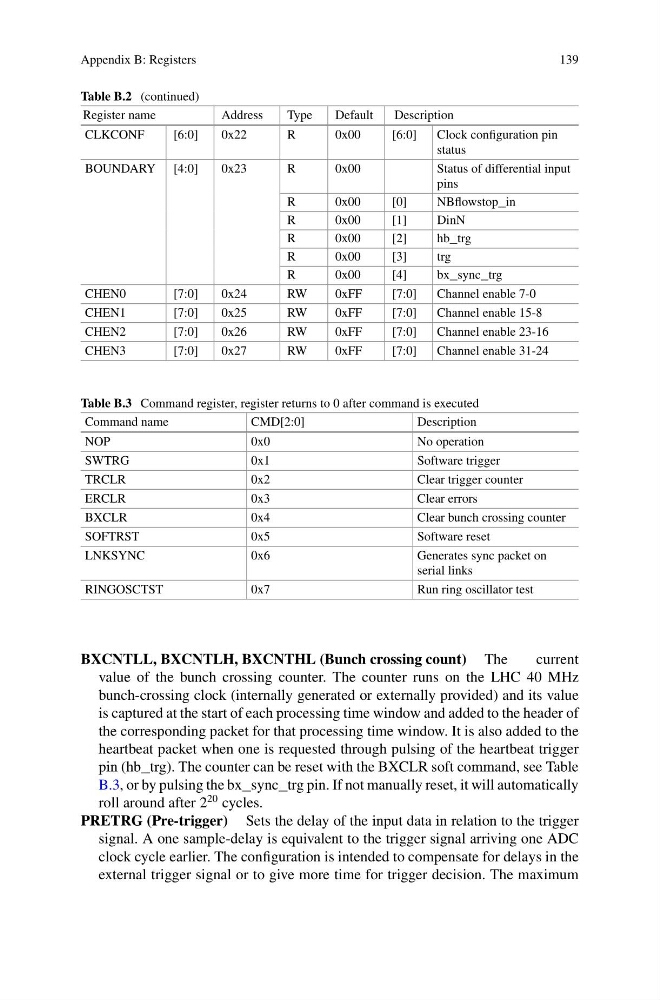
Table B.2 (continued)
Register name
Address
Type
Default
Description
CLKCONF
[6:0]
0x22
R
0x00
[6:0]
Clock configuration pin
status
BOUNDARY [4:0]
0x23
R
0x00
Status of differential input
pins
R
0x00
[0]
NBflowstop_in
R
0x00
[1]
DinN
R
0x00
[2]
hb_trg
R
0x00
[3]
trg
R
0x00
[4]
bx_sync_trg
CHEN0
[7:0]
0x24
RW
0xFF
[7:0]
Channel enable 7-0
CHEN1
[7:0]
0x25
RW
0xFF
[7:0]
Channel enable 15-8
CHEN2
[7:0]
0x26
RW
0xFF
[7:0]
Channel enable 23-16
CHEN3
[7:0]
0x27
RW
0xFF
[7:0]
Channel enable 31-24
Table B.3 Command register, register returns to 0 after command is executed
Command name
CMD[2:0]
Description
NOP
0x0
No operation
SWTRG
0x1
Software trigger
TRCLR
0x2
Clear trigger counter
ERCLR
0x3
Clear errors
BXCLR
0x4
Clear bunch crossing counter
SOFTRST
0x5
Software reset
LNKSYNC
0x6
Generates sync packet on
serial links
RINGOSCTST
0x7
Run ring oscillator test
BXCNTLL, BXCNTLH, BXCNTHL (Bunch crossing count) The
current
value of the bunch crossing counter. The counter runs on the LHC 40 MHz
bunch-crossing clock (internally generated or externally provided) and its value
is captured at the start of each processing time window and added to the header of
the corresponding packet for that processing time window. It is also added to the
heartbeat packet when one is requested through pulsing of the heartbeat trigger
pin (hb_trg). The counter can be reset with the BXCLR soft command, see Table
B.3, or by pulsing the bx_sync_trg pin. If not manually reset, it will automatically
roll around after 2
20 cycles.
PRETRG (Pre-trigger) Sets the delay of the input data in relation to the trigger
signal. A one sample-delay is equivalent to the trigger signal arriving one ADC
clock cycle earlier. The configuration is intended to compensate for delays in the
external trigger signal or to give more time for trigger decision. The maximum
139
Table B.2 (continued)
Register name
Address
Type
Default
Description
CLKCONF
[6:0]
0x22
R
0x00
[6:0]
Clock configuration pin
status
BOUNDARY [4:0]
0x23
R
0x00
Status of differential input
pins
R
0x00
[0]
NBflowstop_in
R
0x00
[1]
DinN
R
0x00
[2]
hb_trg
R
0x00
[3]
trg
R
0x00
[4]
bx_sync_trg
CHEN0
[7:0]
0x24
RW
0xFF
[7:0]
Channel enable 7-0
CHEN1
[7:0]
0x25
RW
0xFF
[7:0]
Channel enable 15-8
CHEN2
[7:0]
0x26
RW
0xFF
[7:0]
Channel enable 23-16
CHEN3
[7:0]
0x27
RW
0xFF
[7:0]
Channel enable 31-24
Table B.3 Command register, register returns to 0 after command is executed
Command name
CMD[2:0]
Description
NOP
0x0
No operation
SWTRG
0x1
Software trigger
TRCLR
0x2
Clear trigger counter
ERCLR
0x3
Clear errors
BXCLR
0x4
Clear bunch crossing counter
SOFTRST
0x5
Software reset
LNKSYNC
0x6
Generates sync packet on
serial links
RINGOSCTST
0x7
Run ring oscillator test
BXCNTLL, BXCNTLH, BXCNTHL (Bunch crossing count) The
current
value of the bunch crossing counter. The counter runs on the LHC 40 MHz
bunch-crossing clock (internally generated or externally provided) and its value
is captured at the start of each processing time window and added to the header of
the corresponding packet for that processing time window. It is also added to the
heartbeat packet when one is requested through pulsing of the heartbeat trigger
pin (hb_trg). The counter can be reset with the BXCLR soft command, see Table
B.3, or by pulsing the bx_sync_trg pin. If not manually reset, it will automatically
roll around after 2
20 cycles.
PRETRG (Pre-trigger) Sets the delay of the input data in relation to the trigger
signal. A one sample-delay is equivalent to the trigger signal arriving one ADC
clock cycle earlier. The configuration is intended to compensate for delays in the
external trigger signal or to give more time for trigger decision. The maximum