

Appendix B: Registers
137
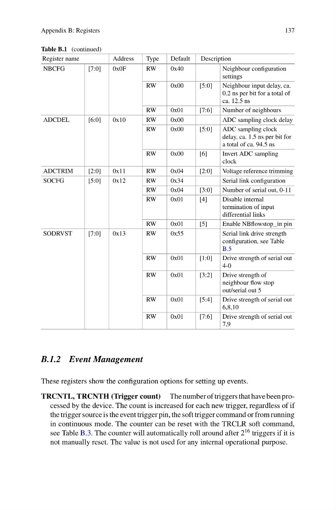
Table B.1 (continued)
Register name
Address
Type
Default
Description
NBCFG
[7:0]
0x0F
RW
0x40
Neighbour configuration
settings
RW
0x00
[5:0]
Neighbour input delay, ca.
0.2 ns per bit for a total of
ca. 12.5 ns
RW
0x01
[7:6]
Number of neighbours
ADCDEL
[6:0]
0x10
RW
0x00
ADC sampling clock delay
RW
0x00
[5:0]
ADC sampling clock
delay, ca. 1.5 ns per bit for
a total of ca. 94.5 ns
RW
0x00
[6]
Invert ADC sampling
clock
ADCTRIM
[2:0]
0x11
RW
0x04
[2:0]
Voltage reference trimming
SOCFG
[5:0]
0x12
RW
0x34
Serial link configuration
RW
0x04
[3:0]
Number of serial out, 0-11
RW
0x01
[4]
Disable internal
termination of input
differential links
RW
0x01
[5]
Enable NBflowstop_in pin
SODRVST
[7:0]
0x13
RW
0x55
Serial link drive strength
configuration, see Table
B.5
RW
0x01
[1:0]
Drive strength of serial out
4-0
RW
0x01
[3:2]
Drive strength of
neighbour flow stop
out/serial out 5
RW
0x01
[5:4]
Drive strength of serial out
6,8,10
RW
0x01
[7:6]
Drive strength of serial out
7,9
B.1.2 Event Management
These registers show the configuration options for setting up events.
TRCNTL, TRCNTH (Trigger count) The number of triggers that have been processed by the device. The count is increased for each new trigger, regardless of if
the trigger source is the event trigger pin, the soft trigger command or from running
in continuous mode. The counter can be reset with the TRCLR soft command,
see Table B.3. The counter will automatically roll around after 2
16 triggers if it is
not manually reset. The value is not used for any internal operational purpose.
137
Table B.1 (continued)
Register name
Address
Type
Default
Description
NBCFG
[7:0]
0x0F
RW
0x40
Neighbour configuration
settings
RW
0x00
[5:0]
Neighbour input delay, ca.
0.2 ns per bit for a total of
ca. 12.5 ns
RW
0x01
[7:6]
Number of neighbours
ADCDEL
[6:0]
0x10
RW
0x00
ADC sampling clock delay
RW
0x00
[5:0]
ADC sampling clock
delay, ca. 1.5 ns per bit for
a total of ca. 94.5 ns
RW
0x00
[6]
Invert ADC sampling
clock
ADCTRIM
[2:0]
0x11
RW
0x04
[2:0]
Voltage reference trimming
SOCFG
[5:0]
0x12
RW
0x34
Serial link configuration
RW
0x04
[3:0]
Number of serial out, 0-11
RW
0x01
[4]
Disable internal
termination of input
differential links
RW
0x01
[5]
Enable NBflowstop_in pin
SODRVST
[7:0]
0x13
RW
0x55
Serial link drive strength
configuration, see Table
B.5
RW
0x01
[1:0]
Drive strength of serial out
4-0
RW
0x01
[3:2]
Drive strength of
neighbour flow stop
out/serial out 5
RW
0x01
[5:4]
Drive strength of serial out
6,8,10
RW
0x01
[7:6]
Drive strength of serial out
7,9
B.1.2 Event Management
These registers show the configuration options for setting up events.
TRCNTL, TRCNTH (Trigger count) The number of triggers that have been processed by the device. The count is increased for each new trigger, regardless of if
the trigger source is the event trigger pin, the soft trigger command or from running
in continuous mode. The counter can be reset with the TRCLR soft command,
see Table B.3. The counter will automatically roll around after 2
16 triggers if it is
not manually reset. The value is not used for any internal operational purpose.