

82
3 SAMPA Chip Implementation
Ring oscillator clock
Count enable
D Q
async
D Q
async
D Q
async
D Q
async
D Q
async
1
0
+
1
9
+
0x0FF
-
<>1
10
10
001
110
0x7F
0x80
[9:7]
[7:0]
D Q
E
Reset (n)
Clock
Enable ring oscillator test
Test done
Reset (n)
Clock
D Q
Test done
Test running
Ring count
8
8
3
10
8
9
9
9
Test running
102 inverters
total
Test running
Signal for disabling during scan chain operation
Ring oscillator clock
Ring oscillator
Reset (n)
Clock
D Q
Test done
1
0
1
0
+
1
Test done
0
8
8
8
8
8
8
1
Enable ring oscillator test
Test running
Count 10MHz cycles
Divide ring oscillator by 16
Count ring oscillator cycles
Compare cycles with overflow handling
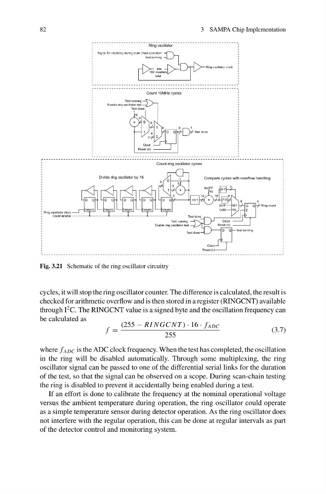
Fig. 3.21 Schematic of the ring oscillator circuitry
cycles, it will stop the ring oscillator counter. The difference is calculated, the result is
checked for arithmetic overflow and is then stored in a register (RINGCNT) available
through I
2 C. The RINGCNT value is a signed byte and the oscillation frequency can
be calculated as
f =
(255 − R I N GC N T ) · 16 · f ADC
255
(3.7)
where f ADC is the ADC clock frequency. When the test has completed, the oscillation
in the ring will be disabled automatically. Through some multiplexing, the ring
oscillator signal can be passed to one of the differential serial links for the duration
of the test, so that the signal can be observed on a scope. During scan-chain testing
the ring is disabled to prevent it accidentally being enabled during a test.
If an effort is done to calibrate the frequency at the nominal operational voltage
versus the ambient temperature during operation, the ring oscillator could operate
as a simple temperature sensor during detector operation. As the ring oscillator does
not interfere with the regular operation, this can be done at regular intervals as part
of the detector control and monitoring system.
3 SAMPA Chip Implementation
Ring oscillator clock
Count enable
D Q
async
D Q
async
D Q
async
D Q
async
D Q
async
1
0
+
1
9
+
0x0FF
-
<>1
10
10
001
110
0x7F
0x80
[9:7]
[7:0]
D Q
E
Reset (n)
Clock
Enable ring oscillator test
Test done
Reset (n)
Clock
D Q
Test done
Test running
Ring count
8
8
3
10
8
9
9
9
Test running
102 inverters
total
Test running
Signal for disabling during scan chain operation
Ring oscillator clock
Ring oscillator
Reset (n)
Clock
D Q
Test done
1
0
1
0
+
1
Test done
0
8
8
8
8
8
8
1
Enable ring oscillator test
Test running
Count 10MHz cycles
Divide ring oscillator by 16
Count ring oscillator cycles
Compare cycles with overflow handling
Fig. 3.21 Schematic of the ring oscillator circuitry
cycles, it will stop the ring oscillator counter. The difference is calculated, the result is
checked for arithmetic overflow and is then stored in a register (RINGCNT) available
through I
2 C. The RINGCNT value is a signed byte and the oscillation frequency can
be calculated as
f =
(255 − R I N GC N T ) · 16 · f ADC
255
(3.7)
where f ADC is the ADC clock frequency. When the test has completed, the oscillation
in the ring will be disabled automatically. Through some multiplexing, the ring
oscillator signal can be passed to one of the differential serial links for the duration
of the test, so that the signal can be observed on a scope. During scan-chain testing
the ring is disabled to prevent it accidentally being enabled during a test.
If an effort is done to calibrate the frequency at the nominal operational voltage
versus the ambient temperature during operation, the ring oscillator could operate
as a simple temperature sensor during detector operation. As the ring oscillator does
not interfere with the regular operation, this can be done at regular intervals as part
of the detector control and monitoring system.