

4.7 Intensity-Dependent Refractive Index
115
well. If the beam power is very very large compared to the critical power (P >> P cr ),
the beam breaks up into several small filaments, each one of which contains the same
power approximately equal to P cr . Out of these three, the self-focusing shall remain
the topic of concern and discussion in this section. So far, we have acquired the
basic understanding of self-focusing. Next, we shall discuss how it is pertinent to
zero-index metamaterials.
4.7.2 Intensity Dependence of a Zero Linear Refractive
Index Medium
Equation 4.119 is the most commonly used method to determine the total refractive
index of a nonlinear medium because one mostly deals with natural materials and/or
their alloys. However, the scenario is completely changed, challenging the common
understanding, when the linear refractive index (n 0 ) vanishes, as in a zero-index
metamaterial. In a ZIM, if n 0 → 0, then n 2 → ∞, P cr → 0, z s f → 0. For a nonlinear refractive index tending to infinity, the expansion shown in Eq. 4.118 and the
consequent Eq. 4.119 are rendered invalid [121]. As explained by Reshef et al. [121],
n 2 I does not remain a small perturbation in the refractive index and rather dominates
the linear term n 0 . Hence, in the case of zero refractive index medium, it is best
to use Eq. 4.114 for accurate calculation of n, since it involves χ
(3) and E which
are independent of n 0 . The anomaly of Eq. 4.119 is illustrated in Fig. 4.23 citing the
case of indium tin oxide (ITO) thin film laid on a glass substrate, illuminated at its
zero epsilon wavelength 1240 nm [100, 121]. Here χ
(3) of ITO has been taken to
be 2.16 × 10
−18 m
2 /V
2 [220], and n 0 = 0.44 n 2 = 0.016 cm
2 /GW [121]. There is a
noticeable difference between the curves corresponding to Eqs. 4.119 and 4.114 at
higher intensities, which yields inaccurate values of n for wavelength corresponding
to near-zero refractive index. Hence, under these circumstances, it is advisable to use
Eq. 4.114. ITO is an attractive candidate for nonlinear optical applications on account
of its considerably high nonlinear susceptibility as well as its CMOS compatibility
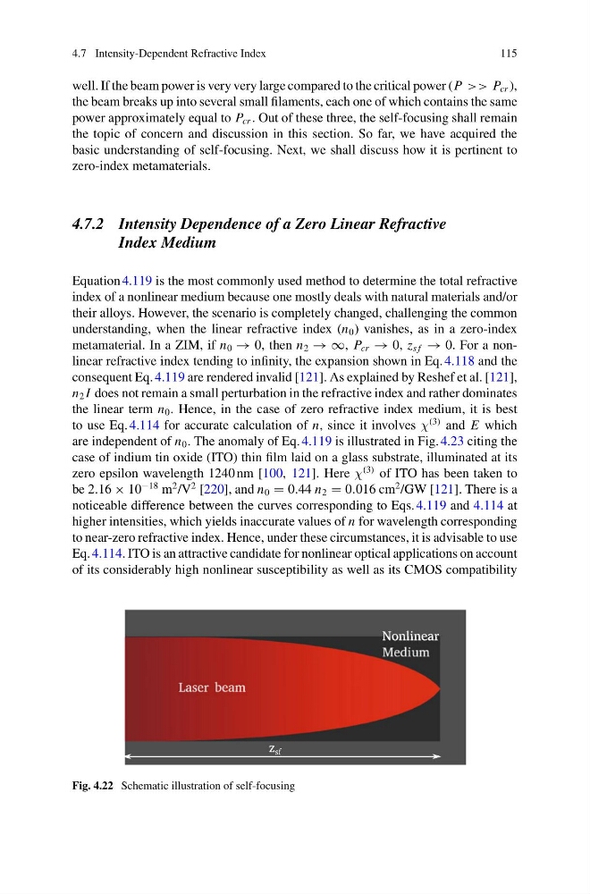
Fig. 4.22 Schematic illustration of self-focusing
115
well. If the beam power is very very large compared to the critical power (P >> P cr ),
the beam breaks up into several small filaments, each one of which contains the same
power approximately equal to P cr . Out of these three, the self-focusing shall remain
the topic of concern and discussion in this section. So far, we have acquired the
basic understanding of self-focusing. Next, we shall discuss how it is pertinent to
zero-index metamaterials.
4.7.2 Intensity Dependence of a Zero Linear Refractive
Index Medium
Equation 4.119 is the most commonly used method to determine the total refractive
index of a nonlinear medium because one mostly deals with natural materials and/or
their alloys. However, the scenario is completely changed, challenging the common
understanding, when the linear refractive index (n 0 ) vanishes, as in a zero-index
metamaterial. In a ZIM, if n 0 → 0, then n 2 → ∞, P cr → 0, z s f → 0. For a nonlinear refractive index tending to infinity, the expansion shown in Eq. 4.118 and the
consequent Eq. 4.119 are rendered invalid [121]. As explained by Reshef et al. [121],
n 2 I does not remain a small perturbation in the refractive index and rather dominates
the linear term n 0 . Hence, in the case of zero refractive index medium, it is best
to use Eq. 4.114 for accurate calculation of n, since it involves χ
(3) and E which
are independent of n 0 . The anomaly of Eq. 4.119 is illustrated in Fig. 4.23 citing the
case of indium tin oxide (ITO) thin film laid on a glass substrate, illuminated at its
zero epsilon wavelength 1240 nm [100, 121]. Here χ
(3) of ITO has been taken to
be 2.16 × 10
−18 m
2 /V
2 [220], and n 0 = 0.44 n 2 = 0.016 cm
2 /GW [121]. There is a
noticeable difference between the curves corresponding to Eqs. 4.119 and 4.114 at
higher intensities, which yields inaccurate values of n for wavelength corresponding
to near-zero refractive index. Hence, under these circumstances, it is advisable to use
Eq. 4.114. ITO is an attractive candidate for nonlinear optical applications on account
of its considerably high nonlinear susceptibility as well as its CMOS compatibility
Fig. 4.22 Schematic illustration of self-focusing