

crystallographic orientation. In this way, the electrons “see” the atoms that are
exactly in a row, although this is useful only if the crystallographic orientation has
low Miller indices. Since, in general, this is not the case, the microscope must be
capable of tilting the specimen, but without losing the point of observation
(eucentric specimen holder). This is a quite a difficult task in the design and
manufacture of the specimen holder.
As mentioned above, the micrographs shown in Figure 12.16 are not “shadow”
images of the lattice, and therefore the interpretation of dark and bright points is not
straightforward. This means that, without a detailed analysis, it cannot be said
whether a dark point shows the position of a column of atoms or a hole. In addition,
artifacts often also disturb lattice images; for example, in the case of high-Z
specimens, due to an enhanced absorption of higher-order diffraction (because
of the larger scattering angle, there will be a longer path through the specimen), the
lattice image may be a function of the specimen thickness.
One very important point here in the interpretation of electron micrographs is the
comparison of bright- and dark-field micrographs of the same spot of specimens.
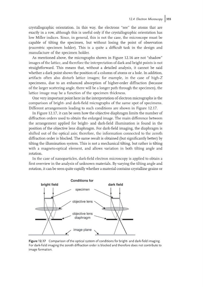
Different arrangements leading to such conditions are shown in Figure 12.17.
In Figure 12.17, it can be seen how the objective diaphragm limits the number of
diffraction orders used to obtain the enlarged image. The main difference between
the arrangement applied for bright- and dark-field illumination is found in the
position of the objective lens diaphragm. For dark-field imaging, the diaphragm is
shifted out of the optical axis; therefore, the information connected to the zeroth
diffraction order is blocked. The same result is obtained (but significantly better) by
tilting the illumination system. This is not a mechanical tilting, but rather is tilting
with a magneto-optical element, and allows variation in both tilting angle and
rotation.
In the case of nanoparticles, dark-field electron microscopy is applied to obtain a
first overview in the analysis of unknown materials. By varying the tilting angle and
rotation, it can be seen quite rapidly whether a material contains crystalline grains or
Figure 12.17 Comparison of the optical system of conditions for bright- and dark-field imaging.
For dark-field imaging the zeroth diffraction order is blocked and therefore does not contribute to
image formation.
12.4 Electron Microscopy j355
exactly in a row, although this is useful only if the crystallographic orientation has
low Miller indices. Since, in general, this is not the case, the microscope must be
capable of tilting the specimen, but without losing the point of observation
(eucentric specimen holder). This is a quite a difficult task in the design and
manufacture of the specimen holder.
As mentioned above, the micrographs shown in Figure 12.16 are not “shadow”
images of the lattice, and therefore the interpretation of dark and bright points is not
straightforward. This means that, without a detailed analysis, it cannot be said
whether a dark point shows the position of a column of atoms or a hole. In addition,
artifacts often also disturb lattice images; for example, in the case of high-Z
specimens, due to an enhanced absorption of higher-order diffraction (because
of the larger scattering angle, there will be a longer path through the specimen), the
lattice image may be a function of the specimen thickness.
One very important point here in the interpretation of electron micrographs is the
comparison of bright- and dark-field micrographs of the same spot of specimens.
Different arrangements leading to such conditions are shown in Figure 12.17.
In Figure 12.17, it can be seen how the objective diaphragm limits the number of
diffraction orders used to obtain the enlarged image. The main difference between
the arrangement applied for bright- and dark-field illumination is found in the
position of the objective lens diaphragm. For dark-field imaging, the diaphragm is
shifted out of the optical axis; therefore, the information connected to the zeroth
diffraction order is blocked. The same result is obtained (but significantly better) by
tilting the illumination system. This is not a mechanical tilting, but rather is tilting
with a magneto-optical element, and allows variation in both tilting angle and
rotation.
In the case of nanoparticles, dark-field electron microscopy is applied to obtain a
first overview in the analysis of unknown materials. By varying the tilting angle and
rotation, it can be seen quite rapidly whether a material contains crystalline grains or
Figure 12.17 Comparison of the optical system of conditions for bright- and dark-field imaging.
For dark-field imaging the zeroth diffraction order is blocked and therefore does not contribute to
image formation.
12.4 Electron Microscopy j355