

Even higher strength and huge strains were obtained by Dalton et al. [33] with
single-wall carbon nanotube composites bound together by an interphase region
consisting of polyvinyl alcohol forming a coating on the nanotubes. The stress–
strain diagram of such a composite specimen, produced in lengths up to 100 m and
with a diameter of 50 mm, is shown in Figure 11.41. In Figure 11.41, for comparison,
the authors included a stress–strain diagram for spider silk – the fiber known to have
the greatest strength among natural products.
0
0.03
0.06
0.09
0.12
0
0.3
0.6
0.9
1.2
stress - strain curve
elastic region
strain Δl/l
stress [GPa]
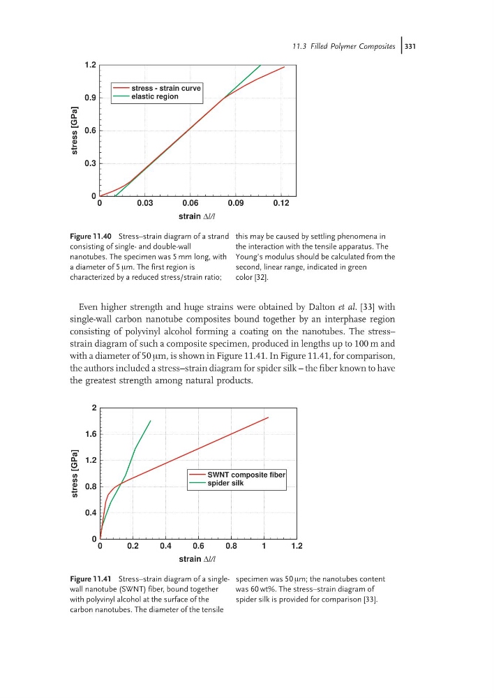
Figure 11.40 Stress–strain diagram of a strand
consisting of single- and double-wall
nanotubes. The specimen was 5 mm long, with
a diameter of 5 mm. The first region is
characterized by a reduced stress/strain ratio;
this may be caused by settling phenomena in
the interaction with the tensile apparatus. The
Young’s modulus should be calculated from the
second, linear range, indicated in green
color [32].
0
0.2
0.4
0.6
0.8
1
1.2
0
0.4
0.8
1.2
1.6
2
SWNT composite fiber
spider silk
strain Δl/l
stress [GPa]
Figure 11.41 Stress–strain diagram of a singlewall nanotube (SWNT) fiber, bound together
with polyvinyl alcohol at the surface of the
carbon nanotubes. The diameter of the tensile
specimen was 50 mm; the nanotubes content
was 60 wt%. The stress–strain diagram of
spider silk is provided for comparison [33].
11.3 Filled Polymer Composites j331
single-wall carbon nanotube composites bound together by an interphase region
consisting of polyvinyl alcohol forming a coating on the nanotubes. The stress–
strain diagram of such a composite specimen, produced in lengths up to 100 m and
with a diameter of 50 mm, is shown in Figure 11.41. In Figure 11.41, for comparison,
the authors included a stress–strain diagram for spider silk – the fiber known to have
the greatest strength among natural products.
0
0.03
0.06
0.09
0.12
0
0.3
0.6
0.9
1.2
stress - strain curve
elastic region
strain Δl/l
stress [GPa]
Figure 11.40 Stress–strain diagram of a strand
consisting of single- and double-wall
nanotubes. The specimen was 5 mm long, with
a diameter of 5 mm. The first region is
characterized by a reduced stress/strain ratio;
this may be caused by settling phenomena in
the interaction with the tensile apparatus. The
Young’s modulus should be calculated from the
second, linear range, indicated in green
color [32].
0
0.2
0.4
0.6
0.8
1
1.2
0
0.4
0.8
1.2
1.6
2
SWNT composite fiber
spider silk
strain Δl/l
stress [GPa]
Figure 11.41 Stress–strain diagram of a singlewall nanotube (SWNT) fiber, bound together
with polyvinyl alcohol at the surface of the
carbon nanotubes. The diameter of the tensile
specimen was 50 mm; the nanotubes content
was 60 wt%. The stress–strain diagram of
spider silk is provided for comparison [33].
11.3 Filled Polymer Composites j331