

The most successful development in the direction of nanocomposites was that of
coated particles, as both the kernel and coating material are distributed homogeneously on a nanometer scale. The particles produced in a first reaction step are
coated with the distance-holder phase in a second reaction step. Two typical
examples of coated nanoparticles are shown in Figure 2.9. In Figure 2.9a, a
ceramic–polymer composite is shown in which the core consists of iron oxide
(c-Fe 2 O 3 ) and the coating of poly(methyl methacrylate) (PMMA). The second
example, a ceramic–ceramic composite, uses a second ceramic phase for coating;
here, the core consists of crystallized zirconia and the coating consists of
amorphous alumina. It is a necessary prerequisite for this type of coated particle
that there is no mutual solubility between the compounds used for the core
and the coating. Figure 2.9b shows three alumina-coated zirconia particles, where
the center particle originates from the coagulation of two zirconia particles. As
the process of coagulation was incomplete, concave areas of the zirconia core
were visible. However, during the coating process these concave areas were filled
with alumina, such that the final coated particle had only convex surfaces. This led
to a minimization of the surface energy, which is an important principle in
nanomaterials.
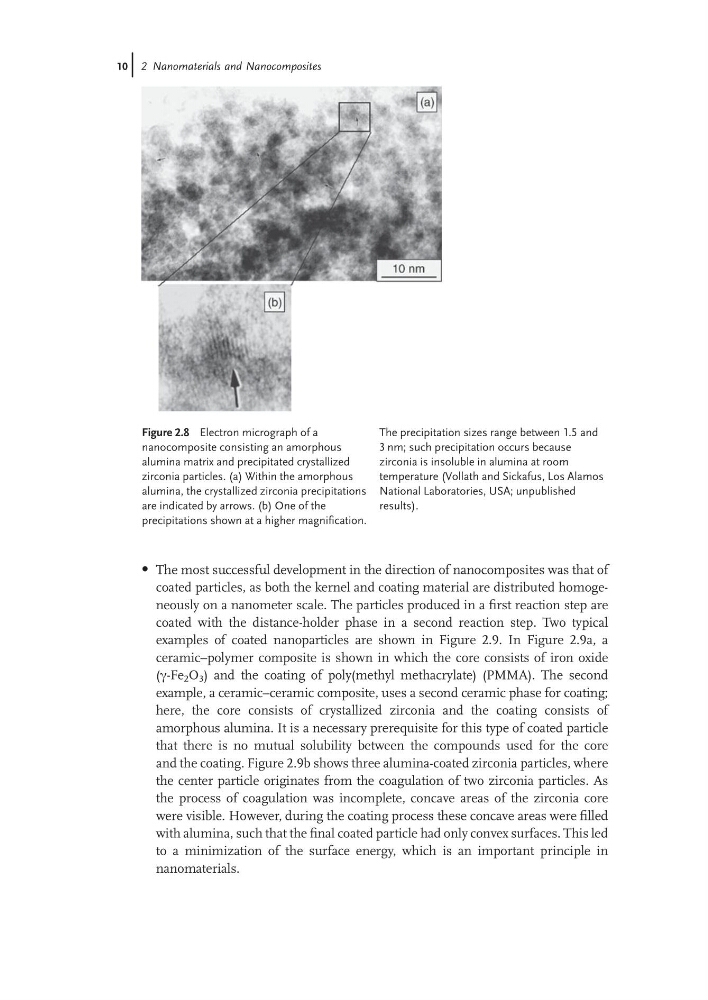
Figure 2.8 Electron micrograph of a
nanocomposite consisting an amorphous
alumina matrix and precipitated crystallized
zirconia particles. (a) Within the amorphous
alumina, the crystallized zirconia precipitations
are indicated by arrows. (b) One of the
precipitations shown at a higher magnification.
The precipitation sizes range between 1.5 and
3 nm; such precipitation occurs because
zirconia is insoluble in alumina at room
temperature (Vollath and Sickafus, Los Alamos
National Laboratories, USA; unpublished
results).
10j 2 Nanomaterials and Nanocomposites
coated particles, as both the kernel and coating material are distributed homogeneously on a nanometer scale. The particles produced in a first reaction step are
coated with the distance-holder phase in a second reaction step. Two typical
examples of coated nanoparticles are shown in Figure 2.9. In Figure 2.9a, a
ceramic–polymer composite is shown in which the core consists of iron oxide
(c-Fe 2 O 3 ) and the coating of poly(methyl methacrylate) (PMMA). The second
example, a ceramic–ceramic composite, uses a second ceramic phase for coating;
here, the core consists of crystallized zirconia and the coating consists of
amorphous alumina. It is a necessary prerequisite for this type of coated particle
that there is no mutual solubility between the compounds used for the core
and the coating. Figure 2.9b shows three alumina-coated zirconia particles, where
the center particle originates from the coagulation of two zirconia particles. As
the process of coagulation was incomplete, concave areas of the zirconia core
were visible. However, during the coating process these concave areas were filled
with alumina, such that the final coated particle had only convex surfaces. This led
to a minimization of the surface energy, which is an important principle in
nanomaterials.
Figure 2.8 Electron micrograph of a
nanocomposite consisting an amorphous
alumina matrix and precipitated crystallized
zirconia particles. (a) Within the amorphous
alumina, the crystallized zirconia precipitations
are indicated by arrows. (b) One of the
precipitations shown at a higher magnification.
The precipitation sizes range between 1.5 and
3 nm; such precipitation occurs because
zirconia is insoluble in alumina at room
temperature (Vollath and Sickafus, Los Alamos
National Laboratories, USA; unpublished
results).
10j 2 Nanomaterials and Nanocomposites