

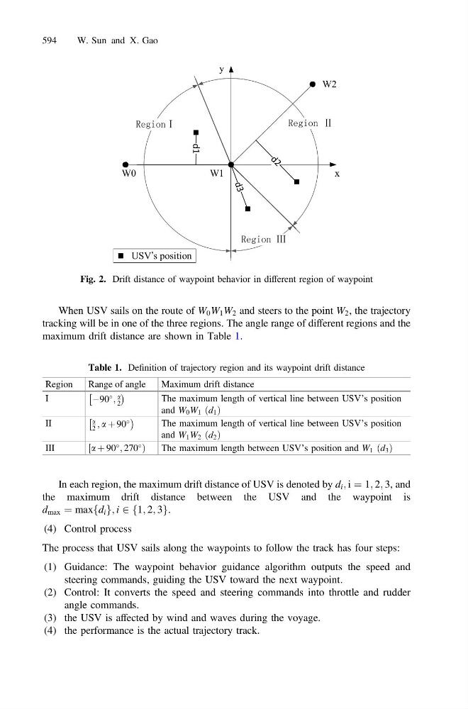
When USV sails on the route of W 0 W 1 W 2 and steers to the point W 2 , the trajectory
tracking will be in one of the three regions. The angle range of different regions and the
maximum drift distance are shown in Table 1.
In each region, the maximum drift distance of USV is denoted by d i ; i ¼ 1; 2; 3, and
the maximum drift distance between the USV and the waypoint is
d max ¼ maxfd i g; i 2 1; 2; 3
f
g.
(4) Control process
The process that USV sails along the waypoints to follow the track has four steps:
(1) Guidance: The waypoint behavior guidance algorithm outputs the speed and
steering commands, guiding the USV toward the next waypoint.
(2) Control: It converts the speed and steering commands into throttle and rudder
angle commands.
(3) the USV is affected by wind and waves during the voyage.
(4) the performance is the actual trajectory track.
x
y
d 2
d1
W2
W1
W0
d 3
USV’s position
Fig. 2. Drift distance of waypoint behavior in different region of waypoint
Table 1. Definition of trajectory region and its waypoint drift distance
Region
Range of angle
Maximum drift distance
I
À90
;
a
2
Â
Á
The maximum length of vertical line between USV’s position
and W 0 W 1 ðd 1 Þ
II
a
2 ; a þ 90
Â
Á
The maximum length of vertical line between USV’s position
and W 1 W 2 ðd 2 Þ
III
a þ 90
; 270
½
Þ
The maximum length between USV’s position and W 1 ðd 3 Þ
594
W. Sun and X. Gao