

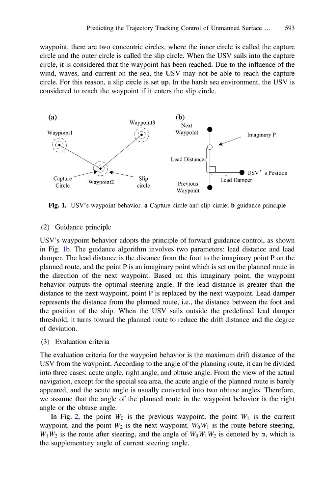
waypoint, there are two concentric circles, where the inner circle is called the capture
circle and the outer circle is called the slip circle. When the USV sails into the capture
circle, it is considered that the waypoint has been reached. Due to the influence of the
wind, waves, and current on the sea, the USV may not be able to reach the capture
circle. For this reason, a slip circle is set up. In the harsh sea environment, the USV is
considered to reach the waypoint if it enters the slip circle.
(2) Guidance principle
USV’s waypoint behavior adopts the principle of forward guidance control, as shown
in Fig. 1b. The guidance algorithm involves two parameters: lead distance and lead
damper. The lead distance is the distance from the foot to the imaginary point P on the
planned route, and the point P is an imaginary point which is set on the planned route in
the direction of the next waypoint. Based on this imaginary point, the waypoint
behavior outputs the optimal steering angle. If the lead distance is greater than the
distance to the next waypoint, point P is replaced by the next waypoint. Lead damper
represents the distance from the planned route, i.e., the distance between the foot and
the position of the ship. When the USV sails outside the predefined lead damper
threshold, it turns toward the planned route to reduce the drift distance and the degree
of deviation.
(3) Evaluation criteria
The evaluation criteria for the waypoint behavior is the maximum drift distance of the
USV from the waypoint. According to the angle of the planning route, it can be divided
into three cases: acute angle, right angle, and obtuse angle. From the view of the actual
navigation, except for the special sea area, the acute angle of the planned route is barely
appeared, and the acute angle is usually converted into two obtuse angles. Therefore,
we assume that the angle of the planned route in the waypoint behavior is the right
angle or the obtuse angle.
In Fig. 2, the point W 0 is the previous waypoint, the point W 1 is the current
waypoint, and the point W 2 is the next waypoint. W 0 W 1 is the route before steering,
W 1 W 2 is the route after steering, and the angle of W 0 W 1 W 2 is denoted by a, which is
the supplementary angle of current steering angle.
Waypoint1
Waypoint2
Slip
circle
Capture
Circle
Waypoint3
(a)
Next
Waypoint
Previous
Waypoint
USV’s Position
Lead Distance
Imaginary P
Lead Damper
(b)
Fig. 1. USV’s waypoint behavior. a Capture circle and slip circle; b guidance principle
Predicting the Trajectory Tracking Control of Unmanned Surface …
593