

X¼
a
ðx
.
L 2 Þ
Y ¼
a
ðy=L 1 Þ
Z ¼
a
ðz
.
L 3 Þ
8
> > > > <
> > > > :
ð4Þ
X, Y, Z denotes the grid coordinates, numerically annotate the grid coordinate
boundary of each node and its internal region, set the initial value N = 0 of the nonforbidden flight zone grid, the initial value of the no-fly zone grid N = 1, perform the
following operations on the values corresponding to the grid coordinates:
N ¼ N þ 1
ð5Þ
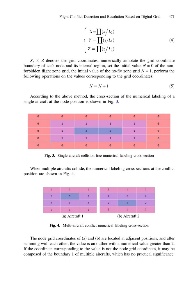
According to the above method, the cross-section of the numerical labeling of a
single aircraft at the node position is shown in Fig. 3.
When multiple aircrafts collide, the numerical labeling cross-sections at the conflict
position are shown in Fig. 4.
The node grid coordinates of (a) and (b) are located at adjacent positions, and after
summing with each other, the value is an outlier with a numerical value greater than 2.
If the coordinate corresponding to the value is not the node grid coordinate, it may be
composed of the boundary 1 of multiple aircrafts, which has no practical significance.
Fig. 3. Single aircraft collision-free numerical labeling cross-section
(a) Aircraft 1
(b) Aircraft 2
Fig. 4. Multi-aircraft conflict numerical labeling cross-section
Flight Conflict Detection and Resolution Based on Digital Grid
471
a
ðx
.
L 2 Þ
Y ¼
a
ðy=L 1 Þ
Z ¼
a
ðz
.
L 3 Þ
8
> > > > <
> > > > :
ð4Þ
X, Y, Z denotes the grid coordinates, numerically annotate the grid coordinate
boundary of each node and its internal region, set the initial value N = 0 of the nonforbidden flight zone grid, the initial value of the no-fly zone grid N = 1, perform the
following operations on the values corresponding to the grid coordinates:
N ¼ N þ 1
ð5Þ
According to the above method, the cross-section of the numerical labeling of a
single aircraft at the node position is shown in Fig. 3.
When multiple aircrafts collide, the numerical labeling cross-sections at the conflict
position are shown in Fig. 4.
The node grid coordinates of (a) and (b) are located at adjacent positions, and after
summing with each other, the value is an outlier with a numerical value greater than 2.
If the coordinate corresponding to the value is not the node grid coordinate, it may be
composed of the boundary 1 of multiple aircrafts, which has no practical significance.
Fig. 3. Single aircraft collision-free numerical labeling cross-section
(a) Aircraft 1
(b) Aircraft 2
Fig. 4. Multi-aircraft conflict numerical labeling cross-section
Flight Conflict Detection and Resolution Based on Digital Grid
471