

3 System Hardware Design
The hardware design of this system is mainly divided into three modules: exhaust fan
control module, data acquisition module, and transmission module.
3.1 Exhaust Fan Control Module
The relay used in the exhaust fan control module is a solid-state relay [2] JGX-5. This
type of relay used in the automatic control circuit is actually an “automatic switch” that
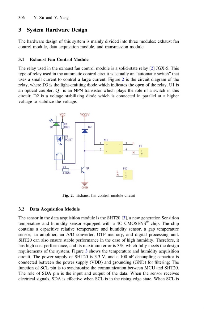
uses a small current to control a large current. Figure 2 is the circuit diagram of the
relay, where D3 is the light-emitting diode which indicates the open of the relay. U1 is
an optical coupler; Q1 is an NPN transistor which plays the role of a switch in this
circuit; D2 is a voltage stabilizing diode which is connected in parallel at a higher
voltage to stabilize the voltage.
3.2 Data Acquisition Module
The sensor in the data acquisition module is the SHT20 [3], a new generation Sensirion
temperature and humidity sensor equipped with a 4C CMOSENS
® chip. The chip
contains a capacitive relative temperature and humidity sensor, a gap temperature
sensor, an amplifier, an A/D converter, OTP memory, and digital processing unit.
SHT20 can also ensure stable performance in the case of high humidity. Therefore, it
has high cost performance, and its maximum error is 3%, which fully meets the design
requirements of the system. Figure 3 shows the temperature and humidity acquisition
circuit. The power supply of SHT20 is 3.3 V, and a 100 nF decoupling capacitor is
connected between the power supply (VDD) and grounding (GND) for filtering; The
function of SCL pin is to synchronize the communication between MCU and SHT20.
The role of SDA pin is the input and output of the data. When the sensor receives
electrical signals, SDA is effective when SCL is in the rising edge state. When SCL is
Fig. 2. Exhaust fan control module circuit
306
Y. Xu and Y. Yang
The hardware design of this system is mainly divided into three modules: exhaust fan
control module, data acquisition module, and transmission module.
3.1 Exhaust Fan Control Module
The relay used in the exhaust fan control module is a solid-state relay [2] JGX-5. This
type of relay used in the automatic control circuit is actually an “automatic switch” that
uses a small current to control a large current. Figure 2 is the circuit diagram of the
relay, where D3 is the light-emitting diode which indicates the open of the relay. U1 is
an optical coupler; Q1 is an NPN transistor which plays the role of a switch in this
circuit; D2 is a voltage stabilizing diode which is connected in parallel at a higher
voltage to stabilize the voltage.
3.2 Data Acquisition Module
The sensor in the data acquisition module is the SHT20 [3], a new generation Sensirion
temperature and humidity sensor equipped with a 4C CMOSENS
® chip. The chip
contains a capacitive relative temperature and humidity sensor, a gap temperature
sensor, an amplifier, an A/D converter, OTP memory, and digital processing unit.
SHT20 can also ensure stable performance in the case of high humidity. Therefore, it
has high cost performance, and its maximum error is 3%, which fully meets the design
requirements of the system. Figure 3 shows the temperature and humidity acquisition
circuit. The power supply of SHT20 is 3.3 V, and a 100 nF decoupling capacitor is
connected between the power supply (VDD) and grounding (GND) for filtering; The
function of SCL pin is to synchronize the communication between MCU and SHT20.
The role of SDA pin is the input and output of the data. When the sensor receives
electrical signals, SDA is effective when SCL is in the rising edge state. When SCL is
Fig. 2. Exhaust fan control module circuit
306
Y. Xu and Y. Yang