

2 Overall Scheme Design of the System
This paper designs an intelligent exhaust fan control system based on STM32, which is
mainly composed of four parts: acquisition terminal nodes, routing nodes, master node,
and monitoring management software. The system model is shown in Fig. 1. The
acquisition terminal nodes are responsible for collecting temperature and humidity
data, processing this data, and transmitting it to the nearby route. The acquisition
terminal nodes can also control the switch of the exhaust fan according to the command
issued by the monitoring management software. The routing nodes are responsible for
monitoring the data of its neighboring acquisition terminal nodes, receiving and
sending it, and acting as a transit station. The master node is responsible for receiving
and forwarding the routing nodes or collecting the environmental data of the acquisition terminal nodes. Monitoring management software consists of two parts: PC side
management software and mobile side management software. Users cannot only
monitor environmental parameters on the PC side and control the switch of the exhaust
fan, but also realize these functions from the mobile side at any time. It makes the
monitoring and management of the exhaust fan more convenient.
The system has the characteristics of self-organization and non-centrality. The
network can be reconfigured automatically without relying on the network of other
devices. When the number of nodes in the network changes, the routing nodes will be
automatically adjusted to realize the self-organization of the whole network. The
joining or leaving of single or multiple nodes does not affect the operation of the whole
network and increases the practicability of the network.
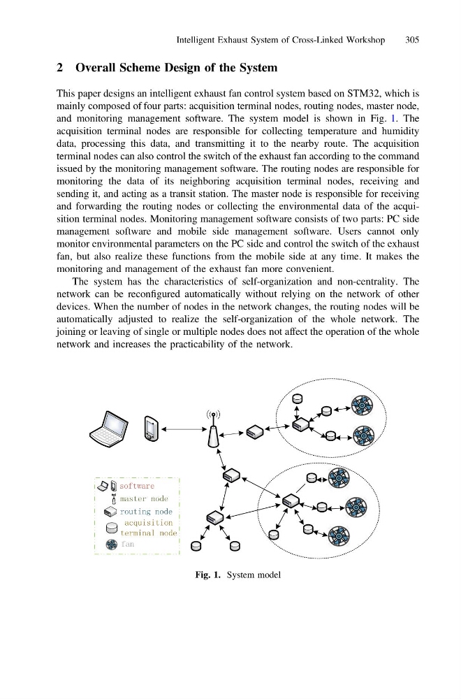
Fig. 1. System model
Intelligent Exhaust System of Cross-Linked Workshop
305
This paper designs an intelligent exhaust fan control system based on STM32, which is
mainly composed of four parts: acquisition terminal nodes, routing nodes, master node,
and monitoring management software. The system model is shown in Fig. 1. The
acquisition terminal nodes are responsible for collecting temperature and humidity
data, processing this data, and transmitting it to the nearby route. The acquisition
terminal nodes can also control the switch of the exhaust fan according to the command
issued by the monitoring management software. The routing nodes are responsible for
monitoring the data of its neighboring acquisition terminal nodes, receiving and
sending it, and acting as a transit station. The master node is responsible for receiving
and forwarding the routing nodes or collecting the environmental data of the acquisition terminal nodes. Monitoring management software consists of two parts: PC side
management software and mobile side management software. Users cannot only
monitor environmental parameters on the PC side and control the switch of the exhaust
fan, but also realize these functions from the mobile side at any time. It makes the
monitoring and management of the exhaust fan more convenient.
The system has the characteristics of self-organization and non-centrality. The
network can be reconfigured automatically without relying on the network of other
devices. When the number of nodes in the network changes, the routing nodes will be
automatically adjusted to realize the self-organization of the whole network. The
joining or leaving of single or multiple nodes does not affect the operation of the whole
network and increases the practicability of the network.
Fig. 1. System model
Intelligent Exhaust System of Cross-Linked Workshop
305