

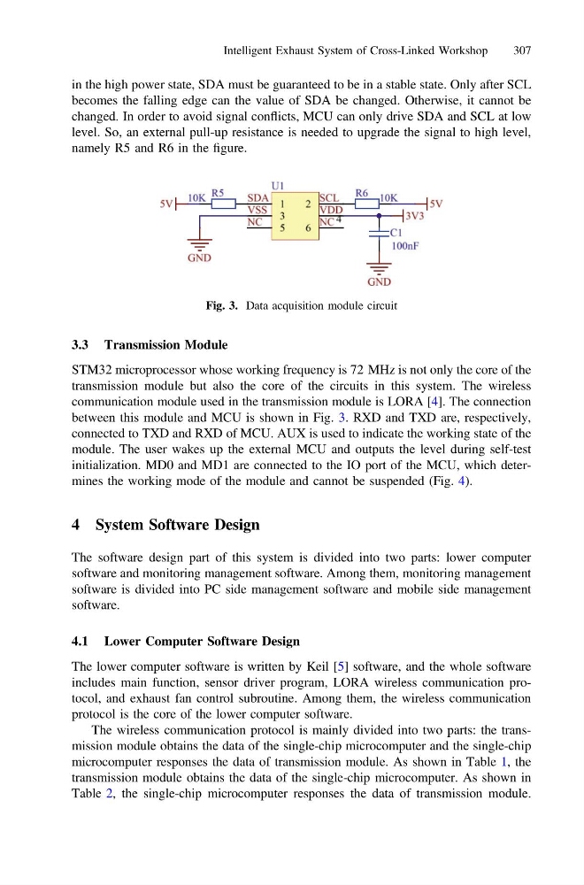
in the high power state, SDA must be guaranteed to be in a stable state. Only after SCL
becomes the falling edge can the value of SDA be changed. Otherwise, it cannot be
changed. In order to avoid signal conflicts, MCU can only drive SDA and SCL at low
level. So, an external pull-up resistance is needed to upgrade the signal to high level,
namely R5 and R6 in the figure.
3.3 Transmission Module
STM32 microprocessor whose working frequency is 72 MHz is not only the core of the
transmission module but also the core of the circuits in this system. The wireless
communication module used in the transmission module is LORA [4]. The connection
between this module and MCU is shown in Fig. 3. RXD and TXD are, respectively,
connected to TXD and RXD of MCU. AUX is used to indicate the working state of the
module. The user wakes up the external MCU and outputs the level during self-test
initialization. MD0 and MD1 are connected to the IO port of the MCU, which determines the working mode of the module and cannot be suspended (Fig. 4).
4 System Software Design
The software design part of this system is divided into two parts: lower computer
software and monitoring management software. Among them, monitoring management
software is divided into PC side management software and mobile side management
software.
4.1 Lower Computer Software Design
The lower computer software is written by Keil [5] software, and the whole software
includes main function, sensor driver program, LORA wireless communication protocol, and exhaust fan control subroutine. Among them, the wireless communication
protocol is the core of the lower computer software.
The wireless communication protocol is mainly divided into two parts: the transmission module obtains the data of the single-chip microcomputer and the single-chip
microcomputer responses the data of transmission module. As shown in Table 1, the
transmission module obtains the data of the single-chip microcomputer. As shown in
Table 2, the single-chip microcomputer responses the data of transmission module.
Fig. 3. Data acquisition module circuit
Intelligent Exhaust System of Cross-Linked Workshop
307
becomes the falling edge can the value of SDA be changed. Otherwise, it cannot be
changed. In order to avoid signal conflicts, MCU can only drive SDA and SCL at low
level. So, an external pull-up resistance is needed to upgrade the signal to high level,
namely R5 and R6 in the figure.
3.3 Transmission Module
STM32 microprocessor whose working frequency is 72 MHz is not only the core of the
transmission module but also the core of the circuits in this system. The wireless
communication module used in the transmission module is LORA [4]. The connection
between this module and MCU is shown in Fig. 3. RXD and TXD are, respectively,
connected to TXD and RXD of MCU. AUX is used to indicate the working state of the
module. The user wakes up the external MCU and outputs the level during self-test
initialization. MD0 and MD1 are connected to the IO port of the MCU, which determines the working mode of the module and cannot be suspended (Fig. 4).
4 System Software Design
The software design part of this system is divided into two parts: lower computer
software and monitoring management software. Among them, monitoring management
software is divided into PC side management software and mobile side management
software.
4.1 Lower Computer Software Design
The lower computer software is written by Keil [5] software, and the whole software
includes main function, sensor driver program, LORA wireless communication protocol, and exhaust fan control subroutine. Among them, the wireless communication
protocol is the core of the lower computer software.
The wireless communication protocol is mainly divided into two parts: the transmission module obtains the data of the single-chip microcomputer and the single-chip
microcomputer responses the data of transmission module. As shown in Table 1, the
transmission module obtains the data of the single-chip microcomputer. As shown in
Table 2, the single-chip microcomputer responses the data of transmission module.
Fig. 3. Data acquisition module circuit
Intelligent Exhaust System of Cross-Linked Workshop
307