

ðF
opt
RF ; v
opt
BB Þ ¼ arg min c opt À F RF v BB
F
F RF 2 f RF ;
F RF v BB
k
k
2
F ¼ 1
ð13Þ
where f RF is the set of feasible RF precoders, i.e., the set of M BS Â M RF matrices with
constant magnitude entries. Each column f RF is obtained from a dictionary set of j Q ,
which can be defined as
j Q ¼ ½a BS ðw h;1 ; w v;1 Þ; . . .; a BS ðw h;Q h ; w v;Q v Þ
ð14Þ
where Q h and Q v are the quantization times in the corresponding direction for a single
beam coverage area. When each phase shifter is controlled by 2
B , the elements of the
matrix can be written as e
jk Q 2p=2
B for k Q ¼ 0; 1; 2; . . .; 2
B
À 1.
Unfortunately, the complex non-convex nature of feasible set f RF makes the
problem of finding such a projection both analytically and algorithmically intractable.
In order to provide near-optimal solutions to the problem in (13) and reduce the system
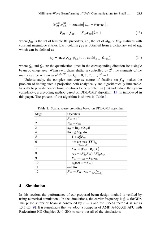
complexity, a precoding method based on DDL-OMP algorithm [15] is introduced in
this paper. The process of the algorithm is shown in Table 1.
4 Simulation
In this section, the performance of our proposed beam design method is verified by
using numerical simulations. In the simulations, the carrier frequency is f c ¼ 60 GHz.
The phase shifter of beam is controlled by B ¼ 3 and the Ricean factor K is set as
13.5 dB [9]. It is remarkable that we adopt a computer of AMD A4-5300B APU with
Radeon(tm) HD Graphics 3.40 GHz to carry out all of the simulations.
Table 1. Spatial sparse precoding based on DDL-OMP algorithm
Stage
Operation
1
F RF = [ ]
2
F res ¼ c opt
3
j Q ¼ [j Q ; s(c opt )]
4
for i M RF do
5
T = j
H
Q F res
6
t ¼ arg max
l¼1; 2; ...; B
ðTT
Ã
Þ l;l
7
F RF ¼ [F RF j Q (:,t)
8
v BB ¼ (F
H
RF F RF )
À1 F
H
RF c opt
9
F res ¼ c opt À F RF v BB
10
j Q (:,tÞ ¼ s(F res )
11
end for
12
F RF ¼ F RF , v BB ¼
vBB
FRFvBB
k
k F
Millimeter-Wave Beamforming of UAV Communications for Small …
285
opt
RF ; v
opt
BB Þ ¼ arg min c opt À F RF v BB
F
F RF 2 f RF ;
F RF v BB
k
k
2
F ¼ 1
ð13Þ
where f RF is the set of feasible RF precoders, i.e., the set of M BS Â M RF matrices with
constant magnitude entries. Each column f RF is obtained from a dictionary set of j Q ,
which can be defined as
j Q ¼ ½a BS ðw h;1 ; w v;1 Þ; . . .; a BS ðw h;Q h ; w v;Q v Þ
ð14Þ
where Q h and Q v are the quantization times in the corresponding direction for a single
beam coverage area. When each phase shifter is controlled by 2
B , the elements of the
matrix can be written as e
jk Q 2p=2
B for k Q ¼ 0; 1; 2; . . .; 2
B
À 1.
Unfortunately, the complex non-convex nature of feasible set f RF makes the
problem of finding such a projection both analytically and algorithmically intractable.
In order to provide near-optimal solutions to the problem in (13) and reduce the system
complexity, a precoding method based on DDL-OMP algorithm [15] is introduced in
this paper. The process of the algorithm is shown in Table 1.
4 Simulation
In this section, the performance of our proposed beam design method is verified by
using numerical simulations. In the simulations, the carrier frequency is f c ¼ 60 GHz.
The phase shifter of beam is controlled by B ¼ 3 and the Ricean factor K is set as
13.5 dB [9]. It is remarkable that we adopt a computer of AMD A4-5300B APU with
Radeon(tm) HD Graphics 3.40 GHz to carry out all of the simulations.
Table 1. Spatial sparse precoding based on DDL-OMP algorithm
Stage
Operation
1
F RF = [ ]
2
F res ¼ c opt
3
j Q ¼ [j Q ; s(c opt )]
4
for i M RF do
5
T = j
H
Q F res
6
t ¼ arg max
l¼1; 2; ...; B
ðTT
Ã
Þ l;l
7
F RF ¼ [F RF j Q (:,t)
8
v BB ¼ (F
H
RF F RF )
À1 F
H
RF c opt
9
F res ¼ c opt À F RF v BB
10
j Q (:,tÞ ¼ s(F res )
11
end for
12
F RF ¼ F RF , v BB ¼
vBB
FRFvBB
k
k F
Millimeter-Wave Beamforming of UAV Communications for Small …
285