

3.2 Optimal Beam Pattern
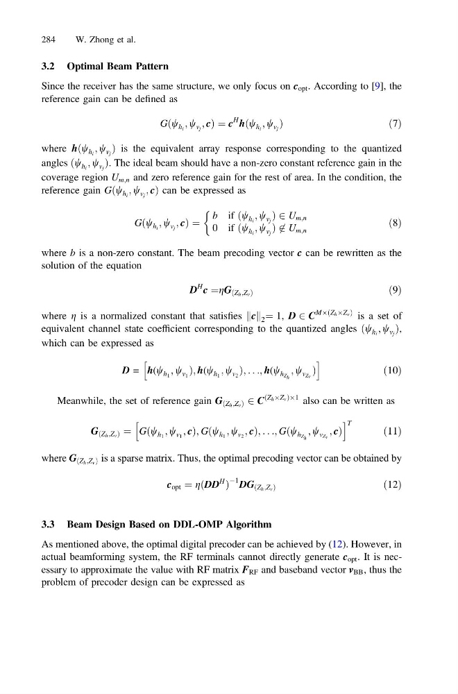
Since the receiver has the same structure, we only focus on c opt . According to [9], the
reference gain can be defined as
Gðw h i ; w v j ; cÞ ¼ c
H
hðw h i ; w v j Þ
ð 7Þ
where hðw h i ; w v j Þ is the equivalent array response corresponding to the quantized
angles ðw h i ; w v j Þ. The ideal beam should have a non-zero constant reference gain in the
coverage region U m;n and zero reference gain for the rest of area. In the condition, the
reference gain Gðw h i ; w v j ; cÞ can be expressed as
Gðw h i ; w v j ; cÞ ¼
b if ðw h i ; w v j Þ 2 U m;n
0 if ðw h i ; w v j Þ 6 2 U m;n
&
ð8Þ
where b is a non-zero constant. The beam precoding vector c can be rewritten as the
solution of the equation
D
H
c ¼gG ðZ h ;Z v Þ
ð9Þ
where g is a normalized constant that satisfies c
k k 2 ¼ 1, D 2 C
MÂðZ h ÂZ v Þ is a set of
equivalent channel state coefficient corresponding to the quantized angles ðw h i ; w v j Þ,
which can be expressed as
D = h(w h 1 ; w v 1 Þ; h(w h 1 ; w v 2 Þ; . . .; h(w h Z h
; w v Zv Þ
h
i
ð10Þ
Meanwhile, the set of reference gain G ðZ h ;Z v Þ 2 C
ðZ h ÂZ v ÞÂ1 also can be written as
G ðZ h ;Z v Þ ¼ Gðw h 1 ; w v 1 ; cÞ; Gðw h 1 ; w v 2 ; cÞ; . . .; Gðw h Z h
; w v Zv ; cÞ
h
i T
ð11Þ
where G ðZ h ;Z v Þ is a sparse matrix. Thus, the optimal precoding vector can be obtained by
c opt ¼ gðDD
H
Þ
À1 DG ðZ h ;Z v Þ
ð12Þ
3.3 Beam Design Based on DDL-OMP Algorithm
As mentioned above, the optimal digital precoder can be achieved by (12). However, in
actual beamforming system, the RF terminals cannot directly generate c opt . It is necessary to approximate the value with RF matrix F RF and baseband vector v BB , thus the
problem of precoder design can be expressed as
284
W. Zhong et al.
Since the receiver has the same structure, we only focus on c opt . According to [9], the
reference gain can be defined as
Gðw h i ; w v j ; cÞ ¼ c
H
hðw h i ; w v j Þ
ð 7Þ
where hðw h i ; w v j Þ is the equivalent array response corresponding to the quantized
angles ðw h i ; w v j Þ. The ideal beam should have a non-zero constant reference gain in the
coverage region U m;n and zero reference gain for the rest of area. In the condition, the
reference gain Gðw h i ; w v j ; cÞ can be expressed as
Gðw h i ; w v j ; cÞ ¼
b if ðw h i ; w v j Þ 2 U m;n
0 if ðw h i ; w v j Þ 6 2 U m;n
&
ð8Þ
where b is a non-zero constant. The beam precoding vector c can be rewritten as the
solution of the equation
D
H
c ¼gG ðZ h ;Z v Þ
ð9Þ
where g is a normalized constant that satisfies c
k k 2 ¼ 1, D 2 C
MÂðZ h ÂZ v Þ is a set of
equivalent channel state coefficient corresponding to the quantized angles ðw h i ; w v j Þ,
which can be expressed as
D = h(w h 1 ; w v 1 Þ; h(w h 1 ; w v 2 Þ; . . .; h(w h Z h
; w v Zv Þ
h
i
ð10Þ
Meanwhile, the set of reference gain G ðZ h ;Z v Þ 2 C
ðZ h ÂZ v ÞÂ1 also can be written as
G ðZ h ;Z v Þ ¼ Gðw h 1 ; w v 1 ; cÞ; Gðw h 1 ; w v 2 ; cÞ; . . .; Gðw h Z h
; w v Zv ; cÞ
h
i T
ð11Þ
where G ðZ h ;Z v Þ is a sparse matrix. Thus, the optimal precoding vector can be obtained by
c opt ¼ gðDD
H
Þ
À1 DG ðZ h ;Z v Þ
ð12Þ
3.3 Beam Design Based on DDL-OMP Algorithm
As mentioned above, the optimal digital precoder can be achieved by (12). However, in
actual beamforming system, the RF terminals cannot directly generate c opt . It is necessary to approximate the value with RF matrix F RF and baseband vector v BB , thus the
problem of precoder design can be expressed as
284
W. Zhong et al.