

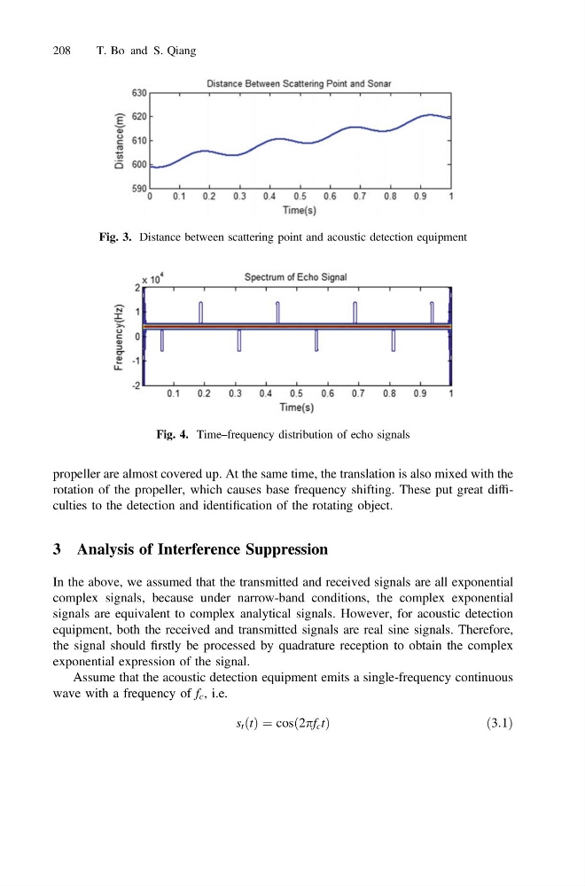
propeller are almost covered up. At the same time, the translation is also mixed with the
rotation of the propeller, which causes base frequency shifting. These put great difficulties to the detection and identification of the rotating object.
3 Analysis of Interference Suppression
In the above, we assumed that the transmitted and received signals are all exponential
complex signals, because under narrow-band conditions, the complex exponential
signals are equivalent to complex analytical signals. However, for acoustic detection
equipment, both the received and transmitted signals are real sine signals. Therefore,
the signal should firstly be processed by quadrature reception to obtain the complex
exponential expression of the signal.
Assume that the acoustic detection equipment emits a single-frequency continuous
wave with a frequency of f c , i.e.
s t ðtÞ ¼ cosð2pf c tÞ
ð 3:1Þ
Fig. 3. Distance between scattering point and acoustic detection equipment
Fig. 4. Time–frequency distribution of echo signals
208
T. Bo and S. Qiang
rotation of the propeller, which causes base frequency shifting. These put great difficulties to the detection and identification of the rotating object.
3 Analysis of Interference Suppression
In the above, we assumed that the transmitted and received signals are all exponential
complex signals, because under narrow-band conditions, the complex exponential
signals are equivalent to complex analytical signals. However, for acoustic detection
equipment, both the received and transmitted signals are real sine signals. Therefore,
the signal should firstly be processed by quadrature reception to obtain the complex
exponential expression of the signal.
Assume that the acoustic detection equipment emits a single-frequency continuous
wave with a frequency of f c , i.e.
s t ðtÞ ¼ cosð2pf c tÞ
ð 3:1Þ
Fig. 3. Distance between scattering point and acoustic detection equipment
Fig. 4. Time–frequency distribution of echo signals
208
T. Bo and S. Qiang