

2.3 Characterisation Techniques
51
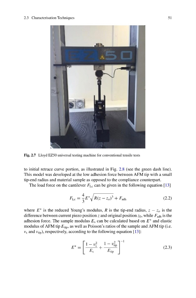
Fig. 2.7 Lloyd EZ50 universal testing machine for conventional tensile tests
to initial retrace curve portion, as illustrated in Fig. 2.8 (see the green dash line).
This model was developed at the low adhesion force between AFM tip with a small
tip-end radius and material sample as opposed to the compliance counterpart.
The load force on the cantilever F Lc can be given in the following equation [13]
F Lc =
4
3
E
∗
R(z − z o )
3
+ F adh
(2.2)
where E
∗ is the reduced Young’s modulus, R is the tip-end radius, z − z o is the
difference between current piezo position z and original position z 0 , while F adh is the
adhesion force. The sample modulus E s can be calculated based on E
∗ and elastic
modulus of AFM tip E tip , as well as Poisson’s ratios of the sample and AFM tip (i.e.
v s and v tip ), respectively, according to the following equation [13]:
E
∗
=
1 − v
2
s
E s
+
1 − v
2
tip
E tip
−1
(2.3)
51
Fig. 2.7 Lloyd EZ50 universal testing machine for conventional tensile tests
to initial retrace curve portion, as illustrated in Fig. 2.8 (see the green dash line).
This model was developed at the low adhesion force between AFM tip with a small
tip-end radius and material sample as opposed to the compliance counterpart.
The load force on the cantilever F Lc can be given in the following equation [13]
F Lc =
4
3
E
∗
R(z − z o )
3
+ F adh
(2.2)
where E
∗ is the reduced Young’s modulus, R is the tip-end radius, z − z o is the
difference between current piezo position z and original position z 0 , while F adh is the
adhesion force. The sample modulus E s can be calculated based on E
∗ and elastic
modulus of AFM tip E tip , as well as Poisson’s ratios of the sample and AFM tip (i.e.
v s and v tip ), respectively, according to the following equation [13]:
E
∗
=
1 − v
2
s
E s
+
1 − v
2
tip
E tip
−1
(2.3)