

262
A. R. Jupp
a)
b)
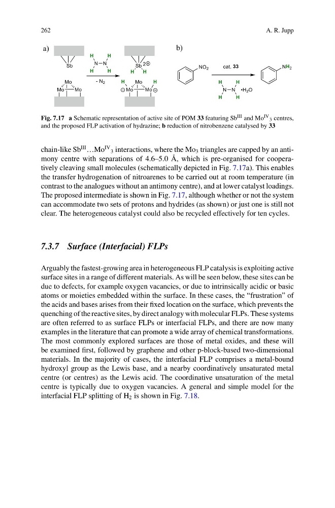
Fig. 7.17 a Schematic representation of active site of POM 33 featuring Sb III and Mo IV 3 centres,
and the proposed FLP activation of hydrazine; b reduction of nitrobenzene catalysed by 33
chain-like Sb
III …Mo
IV
3 interactions, where the Mo 3 triangles are capped by an antimony centre with separations of 4.6–5.0 Å, which is pre-organised for cooperatively cleaving small molecules (schematically depicted in Fig. 7.17a). This enables
the transfer hydrogenation of nitroarenes to be carried out at room temperature (in
contrast to the analogues without an antimony centre), and at lower catalyst loadings.
The proposed intermediate is shown in Fig. 7.17, although whether or not the system
can accommodate two sets of protons and hydrides (as shown) or just one is still not
clear. The heterogeneous catalyst could also be recycled effectively for ten cycles.
7.3.7 Surface (Interfacial) FLPs
Arguably the fastest-growing area in heterogeneous FLP catalysis is exploiting active
surface sites in a range of different materials. As will be seen below, these sites can be
due to defects, for example oxygen vacancies, or due to intrinsically acidic or basic
atoms or moieties embedded within the surface. In these cases, the “frustration” of
the acids and bases arises from their fixed location on the surface, which prevents the
quenching of the reactive sites, by direct analogy with molecular FLPs. These systems
are often referred to as surface FLPs or interfacial FLPs, and there are now many
examples in the literature that can promote a wide array of chemical transformations.
The most commonly explored surfaces are those of metal oxides, and these will
be examined first, followed by graphene and other p-block-based two-dimensional
materials. In the majority of cases, the interfacial FLP comprises a metal-bound
hydroxyl group as the Lewis base, and a nearby coordinatively unsaturated metal
centre (or centres) as the Lewis acid. The coordinative unsaturation of the metal
centre is typically due to oxygen vacancies. A general and simple model for the
interfacial FLP splitting of H 2 is shown in Fig. 7.18.
A. R. Jupp
a)
b)
Fig. 7.17 a Schematic representation of active site of POM 33 featuring Sb III and Mo IV 3 centres,
and the proposed FLP activation of hydrazine; b reduction of nitrobenzene catalysed by 33
chain-like Sb
III …Mo
IV
3 interactions, where the Mo 3 triangles are capped by an antimony centre with separations of 4.6–5.0 Å, which is pre-organised for cooperatively cleaving small molecules (schematically depicted in Fig. 7.17a). This enables
the transfer hydrogenation of nitroarenes to be carried out at room temperature (in
contrast to the analogues without an antimony centre), and at lower catalyst loadings.
The proposed intermediate is shown in Fig. 7.17, although whether or not the system
can accommodate two sets of protons and hydrides (as shown) or just one is still not
clear. The heterogeneous catalyst could also be recycled effectively for ten cycles.
7.3.7 Surface (Interfacial) FLPs
Arguably the fastest-growing area in heterogeneous FLP catalysis is exploiting active
surface sites in a range of different materials. As will be seen below, these sites can be
due to defects, for example oxygen vacancies, or due to intrinsically acidic or basic
atoms or moieties embedded within the surface. In these cases, the “frustration” of
the acids and bases arises from their fixed location on the surface, which prevents the
quenching of the reactive sites, by direct analogy with molecular FLPs. These systems
are often referred to as surface FLPs or interfacial FLPs, and there are now many
examples in the literature that can promote a wide array of chemical transformations.
The most commonly explored surfaces are those of metal oxides, and these will
be examined first, followed by graphene and other p-block-based two-dimensional
materials. In the majority of cases, the interfacial FLP comprises a metal-bound
hydroxyl group as the Lewis base, and a nearby coordinatively unsaturated metal
centre (or centres) as the Lewis acid. The coordinative unsaturation of the metal
centre is typically due to oxygen vacancies. A general and simple model for the
interfacial FLP splitting of H 2 is shown in Fig. 7.18.