

3 The Measurements of the Oxygen Reduction Reaction
49
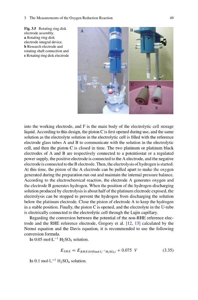
Fig. 3.5 Rotating ring disk
electrode assembly.
a Rotating ring disk
electrode integral device,
b Research electrode and
rotating shaft connection and
c Rotating ring disk electrode
into the working electrode, and F is the main body of the electrolytic cell storage
liquid. According to this design, the piston C is first opened during use, and the same
solution as the electrolyte solution in the electrolytic cell is filled with the reference
electrode glass tubes A and B to communicate with the solution in the electrolytic
cell, and then the piston C is closed in time. The two platinum or platinum black
electrodes of A and B are respectively connected to a potentiostat or a regulated
power supply, the positive electrode is connected to the A electrode, and the negative
electrode is connected to the B electrode. Then, the electrolysis of hydrogen is started.
At this time, the piston of the A electrode can be pulled apart to make the oxygen
generated during the preparation run out and maintain the internal pressure balance.
According to the electrochemical reaction, the electrode A generates oxygen and
the electrode B generates hydrogen. When the position of the hydrogen-discharging
solution produced by electrolysis is about half of the platinum electrode exposed, the
electrolysis can be stopped to prevent the hydrogen from discharging the solution
below the platinum electrode. Close the piston of electrode A to keep the hydrogen
in a stable position. Finally, the piston C is opened, and the electrolyte in the U-tube
is electrically connected to the electrolytic cell through the Lujin capillary.
Regarding the conversion between the potential of the non-RHE reference electrode and the RHE reference electrode, Gregory et al. [12, 13] calculated by the
Nernst equation and the Davis equation, it is recommended to use the following
conversion formula.
In 0.05 mol·L
−1 H 2 SO 4 solution.
E S H E = E R H E(0.05mol L
−1 H 2 SO 4 ) + 0.075 V
(3.35)
In 0.1 mol·L
−1 H 2 SO 4 solution.
49
Fig. 3.5 Rotating ring disk
electrode assembly.
a Rotating ring disk
electrode integral device,
b Research electrode and
rotating shaft connection and
c Rotating ring disk electrode
into the working electrode, and F is the main body of the electrolytic cell storage
liquid. According to this design, the piston C is first opened during use, and the same
solution as the electrolyte solution in the electrolytic cell is filled with the reference
electrode glass tubes A and B to communicate with the solution in the electrolytic
cell, and then the piston C is closed in time. The two platinum or platinum black
electrodes of A and B are respectively connected to a potentiostat or a regulated
power supply, the positive electrode is connected to the A electrode, and the negative
electrode is connected to the B electrode. Then, the electrolysis of hydrogen is started.
At this time, the piston of the A electrode can be pulled apart to make the oxygen
generated during the preparation run out and maintain the internal pressure balance.
According to the electrochemical reaction, the electrode A generates oxygen and
the electrode B generates hydrogen. When the position of the hydrogen-discharging
solution produced by electrolysis is about half of the platinum electrode exposed, the
electrolysis can be stopped to prevent the hydrogen from discharging the solution
below the platinum electrode. Close the piston of electrode A to keep the hydrogen
in a stable position. Finally, the piston C is opened, and the electrolyte in the U-tube
is electrically connected to the electrolytic cell through the Lujin capillary.
Regarding the conversion between the potential of the non-RHE reference electrode and the RHE reference electrode, Gregory et al. [12, 13] calculated by the
Nernst equation and the Davis equation, it is recommended to use the following
conversion formula.
In 0.05 mol·L
−1 H 2 SO 4 solution.
E S H E = E R H E(0.05mol L
−1 H 2 SO 4 ) + 0.075 V
(3.35)
In 0.1 mol·L
−1 H 2 SO 4 solution.