

6 Application of Oxygen Reduction Catalysts
223
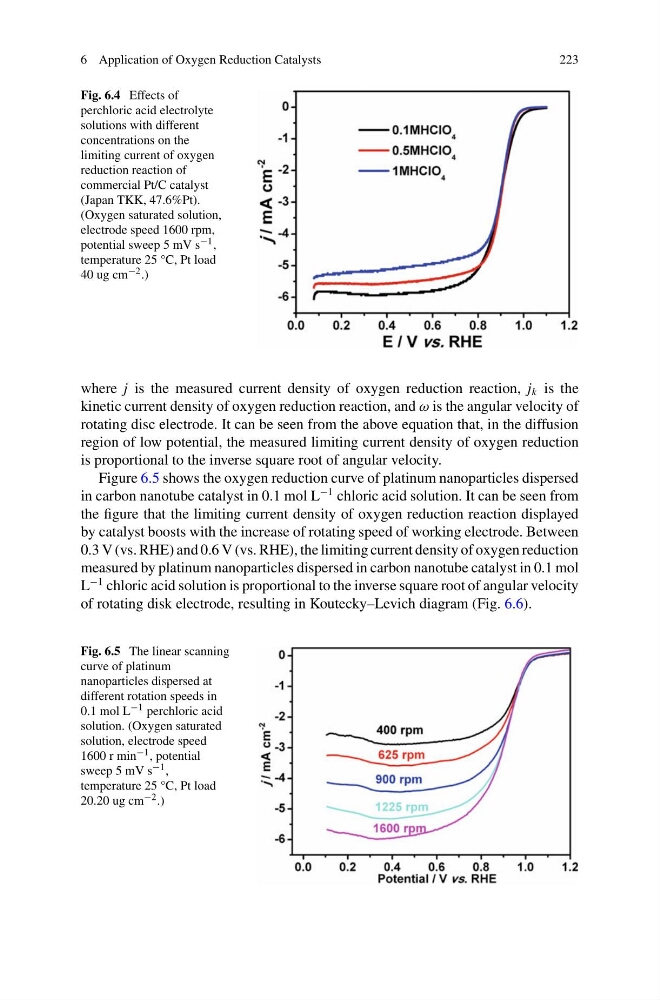
Fig. 6.4 Effects of
perchloric acid electrolyte
solutions with different
concentrations on the
limiting current of oxygen
reduction reaction of
commercial Pt/C catalyst
(Japan TKK, 47.6%Pt).
(Oxygen saturated solution,
electrode speed 1600 rpm,
potential sweep 5 mV s −1 ,
temperature 25 °C, Pt load
40 ug cm −2 .)
where j is the measured current density of oxygen reduction reaction, j k is the
kinetic current density of oxygen reduction reaction, and ω is the angular velocity of
rotating disc electrode. It can be seen from the above equation that, in the diffusion
region of low potential, the measured limiting current density of oxygen reduction
is proportional to the inverse square root of angular velocity.
Figure 6.5 shows the oxygen reduction curve of platinum nanoparticles dispersed
in carbon nanotube catalyst in 0.1 mol L
−1 chloric acid solution. It can be seen from
the figure that the limiting current density of oxygen reduction reaction displayed
by catalyst boosts with the increase of rotating speed of working electrode. Between
0.3 V (vs. RHE) and 0.6 V (vs. RHE), the limiting current density of oxygen reduction
measured by platinum nanoparticles dispersed in carbon nanotube catalyst in 0.1 mol
L
−1 chloric acid solution is proportional to the inverse square root of angular velocity
of rotating disk electrode, resulting in Koutecky–Levich diagram (Fig. 6.6).
Fig. 6.5 The linear scanning
curve of platinum
nanoparticles dispersed at
different rotation speeds in
0.1 mol L −1 perchloric acid
solution. (Oxygen saturated
solution, electrode speed
1600 r min −1 , potential
sweep 5 mV s −1 ,
temperature 25 °C, Pt load
20.20 ug cm −2 .)
223
Fig. 6.4 Effects of
perchloric acid electrolyte
solutions with different
concentrations on the
limiting current of oxygen
reduction reaction of
commercial Pt/C catalyst
(Japan TKK, 47.6%Pt).
(Oxygen saturated solution,
electrode speed 1600 rpm,
potential sweep 5 mV s −1 ,
temperature 25 °C, Pt load
40 ug cm −2 .)
where j is the measured current density of oxygen reduction reaction, j k is the
kinetic current density of oxygen reduction reaction, and ω is the angular velocity of
rotating disc electrode. It can be seen from the above equation that, in the diffusion
region of low potential, the measured limiting current density of oxygen reduction
is proportional to the inverse square root of angular velocity.
Figure 6.5 shows the oxygen reduction curve of platinum nanoparticles dispersed
in carbon nanotube catalyst in 0.1 mol L
−1 chloric acid solution. It can be seen from
the figure that the limiting current density of oxygen reduction reaction displayed
by catalyst boosts with the increase of rotating speed of working electrode. Between
0.3 V (vs. RHE) and 0.6 V (vs. RHE), the limiting current density of oxygen reduction
measured by platinum nanoparticles dispersed in carbon nanotube catalyst in 0.1 mol
L
−1 chloric acid solution is proportional to the inverse square root of angular velocity
of rotating disk electrode, resulting in Koutecky–Levich diagram (Fig. 6.6).
Fig. 6.5 The linear scanning
curve of platinum
nanoparticles dispersed at
different rotation speeds in
0.1 mol L −1 perchloric acid
solution. (Oxygen saturated
solution, electrode speed
1600 r min −1 , potential
sweep 5 mV s −1 ,
temperature 25 °C, Pt load
20.20 ug cm −2 .)