

Nonreflecting Outlet Boundary Conditions for Smoothed Particle Hydrodynamics
69
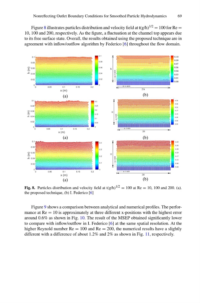
Figure 8 illustrates particles distribution and velocity field at t(g/h) 1/2 = 100 for Re =
10, 100 and 200, respectively. As the figure, a fluctuation at the channel top appears due
to its free surface state. Overall, the results obtained using the proposed technique are in
agreement with inflow/outflow algorithm by Federico [6] throughout the flow domain.
(a)
(b)
(a)
(b)
(a)
(b)
Fig. 8. Particles distribution and velocity field at t(g/h) 1/2 = 100 at Re = 10, 100 and 200. (a).
the proposed technique, (b) I. Federico [6]
Figure 9 shows a comparison between analytical and numerical profiles. The performance at Re = 10 is approximately at three different x-positions with the highest error
around 0.6% as shown in Fig. 10. The result of the MSEP obtained significantly lower
to compare with inflow/outflow in I. Federico [6] at the same spatial resolution. At the
higher Reynold number Re = 100 and Re = 200, the numerical results have a slightly
different with a difference of about 1.2% and 2% as shown in Fig. 11, respectively.
69
Figure 8 illustrates particles distribution and velocity field at t(g/h) 1/2 = 100 for Re =
10, 100 and 200, respectively. As the figure, a fluctuation at the channel top appears due
to its free surface state. Overall, the results obtained using the proposed technique are in
agreement with inflow/outflow algorithm by Federico [6] throughout the flow domain.
(a)
(b)
(a)
(b)
(a)
(b)
Fig. 8. Particles distribution and velocity field at t(g/h) 1/2 = 100 at Re = 10, 100 and 200. (a).
the proposed technique, (b) I. Federico [6]
Figure 9 shows a comparison between analytical and numerical profiles. The performance at Re = 10 is approximately at three different x-positions with the highest error
around 0.6% as shown in Fig. 10. The result of the MSEP obtained significantly lower
to compare with inflow/outflow in I. Federico [6] at the same spatial resolution. At the
higher Reynold number Re = 100 and Re = 200, the numerical results have a slightly
different with a difference of about 1.2% and 2% as shown in Fig. 11, respectively.