

Ultralight Metallic/Composite Materials
23
u 2 (x 1 , x 2 , x 3 ) = u 20 (x 1 ) − ˆ
θ x 3 ,
u 3 (x 1 , x 2 , x 3 ) = u 30 (x 1 ) + ˆ
θ x 2 ,
(1)
where, u 1T (x 2 , x 3 ) is the warping displacement due to the torsion T , u 10 (x 1 ) is the axial
displacement at the centroid (x 2 = x 3 = 0), u 20 (x 1 ) and u 30 (x 1 ) are the transverse
bending displacements at the centroid along x 2 - and x 3 -axes, respectively, and ˆ
θ is the
twist angle around x 1 -axis. Using the Green-Lagrange strain components in the updated
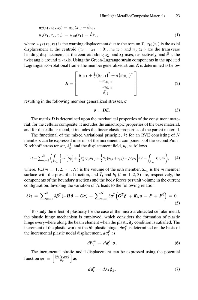
Lagrangian co-rotational frame, the member generalized strain, E is determined as below
E =
⎡
⎢
⎢
⎢
⎣
u 10,1 +
1
2
u 20,1
2 +
1
2
u 30,1
2
−u 20,11
−u 30,11
ˆ
θ ,1
⎤
⎥
⎥
⎥
⎦
,
(2)
resulting in the following member generalized stresses, σ
σ = DE.
(3)
The matrix D is determined upon the mechanical properties of the constituent material; for the cellular composite, it includes the anisotropic properties of the base material,
and for the cellular metal, it includes the linear elastic properties of the parent material.
The functional of the mixed variational principle, H for an RVE consisting of N
members can be expressed in terms of the incremental components of the second PiolaKirchhoff stress tensor, S 1
ij . and the displacement field, u i , as follows
H =
N
m=1
V m
−B
S 1
ij
+
1
2
τ 0
ij u k,i u k,j +
1
2
S ij
u i,j + u j,i
− ρb i u i
dV −
S σm
¯
T i u i dS
,
(4)
where, V m (m = 1, 2, · · · , N ) is the volume of the mth member, S σ m is the m member
surface with the prescribed traction, and ¯
T i and b i (i = 1, 2, 3) are, respectively, the
components of the boundary tractions and the body forces per unit volume in the current
configuration. Invoking the variation of H leads to the following relation
δH =
N
m=1
δβ
T
(−Hβ + Ga) +
N
m=1
δa
T
G
T
β + K N a − F + F
0
= 0.
(5)
To study the effect of plasticity for the case of the micro-architected cellular metal,
the plastic hinge mechanism is employed, which considers the formation of plastic
hinge everywhere along the beam element when the plasticity condition is satisfied. The
increment of the plastic work at the ith plastic hinge, dw P
i is determined on the basis of
the incremental plastic nodal displacement, d a P
i as
dW
p
i = d a
pT
i σ .
(6)
The incremental plastic nodal displacement can be expressed using the potential
function φ k =
∂f k (σ ,σ Y )
∂σ
as
d a
p
i = d λ k φ k ,
(7)
23
u 2 (x 1 , x 2 , x 3 ) = u 20 (x 1 ) − ˆ
θ x 3 ,
u 3 (x 1 , x 2 , x 3 ) = u 30 (x 1 ) + ˆ
θ x 2 ,
(1)
where, u 1T (x 2 , x 3 ) is the warping displacement due to the torsion T , u 10 (x 1 ) is the axial
displacement at the centroid (x 2 = x 3 = 0), u 20 (x 1 ) and u 30 (x 1 ) are the transverse
bending displacements at the centroid along x 2 - and x 3 -axes, respectively, and ˆ
θ is the
twist angle around x 1 -axis. Using the Green-Lagrange strain components in the updated
Lagrangian co-rotational frame, the member generalized strain, E is determined as below
E =
⎡
⎢
⎢
⎢
⎣
u 10,1 +
1
2
u 20,1
2 +
1
2
u 30,1
2
−u 20,11
−u 30,11
ˆ
θ ,1
⎤
⎥
⎥
⎥
⎦
,
(2)
resulting in the following member generalized stresses, σ
σ = DE.
(3)
The matrix D is determined upon the mechanical properties of the constituent material; for the cellular composite, it includes the anisotropic properties of the base material,
and for the cellular metal, it includes the linear elastic properties of the parent material.
The functional of the mixed variational principle, H for an RVE consisting of N
members can be expressed in terms of the incremental components of the second PiolaKirchhoff stress tensor, S 1
ij . and the displacement field, u i , as follows
H =
N
m=1
V m
−B
S 1
ij
+
1
2
τ 0
ij u k,i u k,j +
1
2
S ij
u i,j + u j,i
− ρb i u i
dV −
S σm
¯
T i u i dS
,
(4)
where, V m (m = 1, 2, · · · , N ) is the volume of the mth member, S σ m is the m member
surface with the prescribed traction, and ¯
T i and b i (i = 1, 2, 3) are, respectively, the
components of the boundary tractions and the body forces per unit volume in the current
configuration. Invoking the variation of H leads to the following relation
δH =
N
m=1
δβ
T
(−Hβ + Ga) +
N
m=1
δa
T
G
T
β + K N a − F + F
0
= 0.
(5)
To study the effect of plasticity for the case of the micro-architected cellular metal,
the plastic hinge mechanism is employed, which considers the formation of plastic
hinge everywhere along the beam element when the plasticity condition is satisfied. The
increment of the plastic work at the ith plastic hinge, dw P
i is determined on the basis of
the incremental plastic nodal displacement, d a P
i as
dW
p
i = d a
pT
i σ .
(6)
The incremental plastic nodal displacement can be expressed using the potential
function φ k =
∂f k (σ ,σ Y )
∂σ
as
d a
p
i = d λ k φ k ,
(7)