

296
Y. Xu et al.
4 Results and Discussion
4.1 Verification of Steady-State Simulation Examples of Pipeline Network
In order to verify the accuracy and precision of the model, this paper takes a complex
natural gas gathering pipeline network in the literature [24] as an example to verify. The
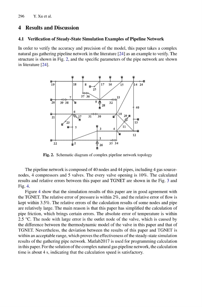
structure is shown in Fig. 2, and the specific parameters of the pipe network are shown
in literature [24].
Fig. 2. Schematic diagram of complex pipeline network topology
The pipeline network is composed of 40 nodes and 44 pipes, including 4 gas sourcenodes, 4 compressors and 5 valves. The every valve opening is 10%. The calculated
results and relative errors between this paper and TGNET are shown in the Fig. 3 and
Fig. 4.
Figure 4 show that the simulation results of this paper are in good agreement with
the TGNET. The relative error of pressure is within 2%, and the relative error of flow is
kept within 3.5%. The relative errors of the calculation results of some nodes and pipe
are relatively large. The main reason is that this paper has simplified the calculation of
pipe friction, which brings certain errors. The absolute error of temperature is within
2.5 °C. The node with large error is the outlet node of the valve, which is caused by
the difference between the thermodynamic model of the valve in this paper and that of
TGNET. Nevertheless, the deviation between the results of this paper and TGNET is
within an acceptable range, which proves the effectiveness of the steady-state simulation
results of the gathering pipe network. Matlab2017 is used for programming calculation
in this paper. For the solution of the complex natural gas pipeline network, the calculation
time is about 4 s, indicating that the calculation speed is satisfactory.
Y. Xu et al.
4 Results and Discussion
4.1 Verification of Steady-State Simulation Examples of Pipeline Network
In order to verify the accuracy and precision of the model, this paper takes a complex
natural gas gathering pipeline network in the literature [24] as an example to verify. The
structure is shown in Fig. 2, and the specific parameters of the pipe network are shown
in literature [24].
Fig. 2. Schematic diagram of complex pipeline network topology
The pipeline network is composed of 40 nodes and 44 pipes, including 4 gas sourcenodes, 4 compressors and 5 valves. The every valve opening is 10%. The calculated
results and relative errors between this paper and TGNET are shown in the Fig. 3 and
Fig. 4.
Figure 4 show that the simulation results of this paper are in good agreement with
the TGNET. The relative error of pressure is within 2%, and the relative error of flow is
kept within 3.5%. The relative errors of the calculation results of some nodes and pipe
are relatively large. The main reason is that this paper has simplified the calculation of
pipe friction, which brings certain errors. The absolute error of temperature is within
2.5 °C. The node with large error is the outlet node of the valve, which is caused by
the difference between the thermodynamic model of the valve in this paper and that of
TGNET. Nevertheless, the deviation between the results of this paper and TGNET is
within an acceptable range, which proves the effectiveness of the steady-state simulation
results of the gathering pipe network. Matlab2017 is used for programming calculation
in this paper. For the solution of the complex natural gas pipeline network, the calculation
time is about 4 s, indicating that the calculation speed is satisfactory.