

230
A. Andersson
4 Numerical Model
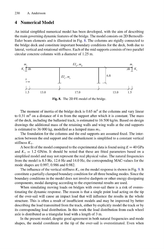
An initial simplified numerical model has been developed, with the aim of describing
the main governing dynamic features of the bridge. The model consists on 2D BernoulliEuler beam elements and is illustrated in Fig. 8. The columns are rigidly connected to
the bridge deck and constitute important boundary conditions for the deck, both due to
lateral, vertical and rotational stiffness. Each of the mid supports consists of two parallel
circular concrete columns with a diameter of 1.25 m.
1.5
13.0
17.0
13.0
1.5
EI d , m d
K v
K v
m 1
m 1
EI c , m c
6.8
x
Fig. 8. The 2D FE-model of the bridge.
The moment of inertia of the bridge deck is 0.65 m 4 at the columns and vary linear
to 0.31 m 4 on a distance of 4 m from the support after which it is constant. The mass
of the deck, including the ballasted track, is estimated to 16 500 kg/m. Based on design
drawings the additional mass of the retaining walls and wing walls at the end supports
is estimated to 36 000 kg, modelled as a lumped mass m 1 .
The foundation for the columns and the end supports are assumed fixed. The interaction between the end support and the embankment is simplified to a constant vertical
stiffness K v .
A best fit of the model compared to the experimental data is found using E = 40 GPa
and K v = 1.2 GN/m. It should be noted that these are fitted parameters based on a
simplified model and may not represent the real physical value. The natural frequencies
from the model is 8.5 Hz, 12.6 Hz and 14.0 Hz, the corresponding MAC-values for the
mode shapes are 0.997, 0.986 and 0.982.
The influence of the vertical stiffness K v on the model response is shown in Fig. 9. It
constitute a partially clamped boundary condition for all three bending modes. Since the
boundary conditions in the model does not involve dashpots or other energy dissipating
components, modal damping according to the experimental results are used.
When simulating moving loads on bridges with over-sail there is a risk of overestimating the dynamic response. The reason is that a single point load acting on the tip
of the over-sail will cause an impact load that will influence the results in the whole
structure. This is often a result of insufficient models and may be improved by better
describing the load transmitted from the track, either by explicitly model the track or by
its corresponding load distribution. In this work the load distribution from each wheel
axle is distributed as a triangular load with a length of 3 m.
In the present model, despite good agreement in both natural frequencies and mode
shapes, the modal coordinate at the tip of the over-sail is overestimated. Even when
A. Andersson
4 Numerical Model
An initial simplified numerical model has been developed, with the aim of describing
the main governing dynamic features of the bridge. The model consists on 2D BernoulliEuler beam elements and is illustrated in Fig. 8. The columns are rigidly connected to
the bridge deck and constitute important boundary conditions for the deck, both due to
lateral, vertical and rotational stiffness. Each of the mid supports consists of two parallel
circular concrete columns with a diameter of 1.25 m.
1.5
13.0
17.0
13.0
1.5
EI d , m d
K v
K v
m 1
m 1
EI c , m c
6.8
x
Fig. 8. The 2D FE-model of the bridge.
The moment of inertia of the bridge deck is 0.65 m 4 at the columns and vary linear
to 0.31 m 4 on a distance of 4 m from the support after which it is constant. The mass
of the deck, including the ballasted track, is estimated to 16 500 kg/m. Based on design
drawings the additional mass of the retaining walls and wing walls at the end supports
is estimated to 36 000 kg, modelled as a lumped mass m 1 .
The foundation for the columns and the end supports are assumed fixed. The interaction between the end support and the embankment is simplified to a constant vertical
stiffness K v .
A best fit of the model compared to the experimental data is found using E = 40 GPa
and K v = 1.2 GN/m. It should be noted that these are fitted parameters based on a
simplified model and may not represent the real physical value. The natural frequencies
from the model is 8.5 Hz, 12.6 Hz and 14.0 Hz, the corresponding MAC-values for the
mode shapes are 0.997, 0.986 and 0.982.
The influence of the vertical stiffness K v on the model response is shown in Fig. 9. It
constitute a partially clamped boundary condition for all three bending modes. Since the
boundary conditions in the model does not involve dashpots or other energy dissipating
components, modal damping according to the experimental results are used.
When simulating moving loads on bridges with over-sail there is a risk of overestimating the dynamic response. The reason is that a single point load acting on the tip
of the over-sail will cause an impact load that will influence the results in the whole
structure. This is often a result of insufficient models and may be improved by better
describing the load transmitted from the track, either by explicitly model the track or by
its corresponding load distribution. In this work the load distribution from each wheel
axle is distributed as a triangular load with a length of 3 m.
In the present model, despite good agreement in both natural frequencies and mode
shapes, the modal coordinate at the tip of the over-sail is overestimated. Even when