

228
A. Andersson
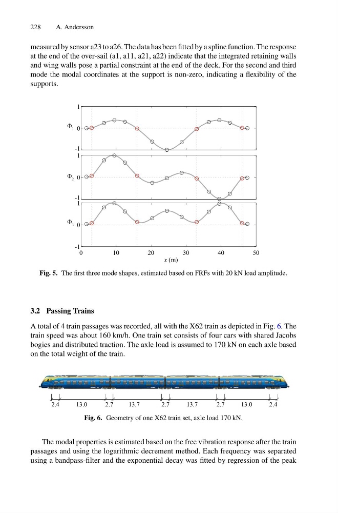
measured by sensor a23 to a26. The data has been fitted by a spline function. The response
at the end of the over-sail (a1, a11, a21, a22) indicate that the integrated retaining walls
and wing walls pose a partial constraint at the end of the deck. For the second and third
mode the modal coordinates at the support is non-zero, indicating a flexibility of the
supports.
-1
0
1
-1
0
1
0
1 0
2 0
3 0
4 0
5 0
x (m)
-1
0
1
Φ 1
Φ 2
Φ 3
Fig. 5. The first three mode shapes, estimated based on FRFs with 20 kN load amplitude.
3.2 Passing Trains
A total of 4 train passages was recorded, all with the X62 train as depicted in Fig. 6. The
train speed was about 160 km/h. One train set consists of four cars with shared Jacobs
bogies and distributed traction. The axle load is assumed to 170 kN on each axle based
on the total weight of the train.
2.4
13.0
2.7
13.7
13.7
2.7
2.7
13.0
2.4
Fig. 6. Geometry of one X62 train set, axle load 170 kN.
The modal properties is estimated based on the free vibration response after the train
passages and using the logarithmic decrement method. Each frequency was separated
using a bandpass-filter and the exponential decay was fitted by regression of the peak
A. Andersson
measured by sensor a23 to a26. The data has been fitted by a spline function. The response
at the end of the over-sail (a1, a11, a21, a22) indicate that the integrated retaining walls
and wing walls pose a partial constraint at the end of the deck. For the second and third
mode the modal coordinates at the support is non-zero, indicating a flexibility of the
supports.
-1
0
1
-1
0
1
0
1 0
2 0
3 0
4 0
5 0
x (m)
-1
0
1
Φ 1
Φ 2
Φ 3
Fig. 5. The first three mode shapes, estimated based on FRFs with 20 kN load amplitude.
3.2 Passing Trains
A total of 4 train passages was recorded, all with the X62 train as depicted in Fig. 6. The
train speed was about 160 km/h. One train set consists of four cars with shared Jacobs
bogies and distributed traction. The axle load is assumed to 170 kN on each axle based
on the total weight of the train.
2.4
13.0
2.7
13.7
13.7
2.7
2.7
13.0
2.4
Fig. 6. Geometry of one X62 train set, axle load 170 kN.
The modal properties is estimated based on the free vibration response after the train
passages and using the logarithmic decrement method. Each frequency was separated
using a bandpass-filter and the exponential decay was fitted by regression of the peak