

Full-Scale Forced Vibration Tests of a Railway Bridge
227
according to Eq. (1). The transfer function is hereafter referred to as the frequency
response function FRF and presented in m/s 2 /kN.
X(ω) = H(ω)F(ω)
(1)
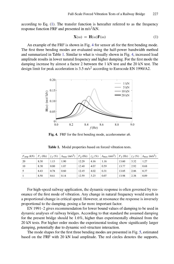
An example of the FRF is shown in Fig. 4 for sensor a6 for the first bending mode.
The first three bending modes are evaluated using the half-power bandwidth method
and summarized in Table 1. Similar to what is visually shown in Fig. 4, increased load
amplitude results in lower natural frequency and higher damping. For the first mode the
damping increase by almost a factor 2 between the 1 kN test and the 20 kN test. The
design limit for peak acceleration is 3.5 m/s 2 according to Eurocode EN 1990/A2.
8.0
8.2
8.4
8.6
8.8
9.0
f (Hz)
0
0.05
0.10
0.15
0.20
1 kN
5 kN
10 kN
20 kN
H(ω) (m/s
2
/kN)
Fig. 4. FRF for the first bending mode, accelerometer a6.
Table 1. Modal properties based on forced vibration tests.
F amp (kN) F 1 (Hz) ζ 1 (%) A max (m/s 2 ) F 2 (Hz) ζ 2 (%) A max (m/s 2 ) F 3 (Hz) ζ 3 (%) A max (m/s 2 )
20
8.30
1.13
1.90
12.29
4.16
1.16
13.60
3.32
1.27
10
8.38
0.80
1.07
12.40
4.07
0.59
13.77
2.92
0.68
5
8.43
0.78
0.60
12.45
4.02
0.31
13.85
2.86
0.37
1
8.50
0.61
0.14
12.59
3.23
0.07
13.98
2.38
0.09
For high-speed railway application, the dynamic response is often governed by resonance of the first mode of vibration. Any change in natural frequency would result in
a proportional change in critical speed. However, at resonance the response is inversely
proportional to the damping, posing a far more important factor.
EN 1991–2 gives recommendation for lower bound values of damping to be used in
dynamic analyses of railway bridges. According to that standard the assumed damping
for the present bridge should be 1.6%, higher than experimentally obtained from the
20 kN tests. For higher order modes the experimental testing show significantly larger
damping, potentially due to dynamic soil-structure interaction.
The mode shapes for the first three bending modes are presented in Fig. 5, estimated
based on the FRF with 20 kN load amplitude. The red circles denotes the supports,
227
according to Eq. (1). The transfer function is hereafter referred to as the frequency
response function FRF and presented in m/s 2 /kN.
X(ω) = H(ω)F(ω)
(1)
An example of the FRF is shown in Fig. 4 for sensor a6 for the first bending mode.
The first three bending modes are evaluated using the half-power bandwidth method
and summarized in Table 1. Similar to what is visually shown in Fig. 4, increased load
amplitude results in lower natural frequency and higher damping. For the first mode the
damping increase by almost a factor 2 between the 1 kN test and the 20 kN test. The
design limit for peak acceleration is 3.5 m/s 2 according to Eurocode EN 1990/A2.
8.0
8.2
8.4
8.6
8.8
9.0
f (Hz)
0
0.05
0.10
0.15
0.20
1 kN
5 kN
10 kN
20 kN
H(ω) (m/s
2
/kN)
Fig. 4. FRF for the first bending mode, accelerometer a6.
Table 1. Modal properties based on forced vibration tests.
F amp (kN) F 1 (Hz) ζ 1 (%) A max (m/s 2 ) F 2 (Hz) ζ 2 (%) A max (m/s 2 ) F 3 (Hz) ζ 3 (%) A max (m/s 2 )
20
8.30
1.13
1.90
12.29
4.16
1.16
13.60
3.32
1.27
10
8.38
0.80
1.07
12.40
4.07
0.59
13.77
2.92
0.68
5
8.43
0.78
0.60
12.45
4.02
0.31
13.85
2.86
0.37
1
8.50
0.61
0.14
12.59
3.23
0.07
13.98
2.38
0.09
For high-speed railway application, the dynamic response is often governed by resonance of the first mode of vibration. Any change in natural frequency would result in
a proportional change in critical speed. However, at resonance the response is inversely
proportional to the damping, posing a far more important factor.
EN 1991–2 gives recommendation for lower bound values of damping to be used in
dynamic analyses of railway bridges. According to that standard the assumed damping
for the present bridge should be 1.6%, higher than experimentally obtained from the
20 kN tests. For higher order modes the experimental testing show significantly larger
damping, potentially due to dynamic soil-structure interaction.
The mode shapes for the first three bending modes are presented in Fig. 5, estimated
based on the FRF with 20 kN load amplitude. The red circles denotes the supports,