

226
A. Andersson
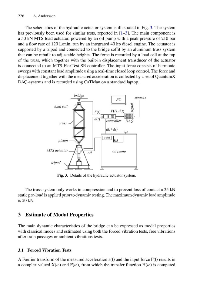
The schematics of the hydraulic actuator system is illustrated in Fig. 3. The system
has previously been used for similar tests, reported in [1–3]. The main component is
a 50 kN MTS load actuator, powered by an oil pump with a peak pressure of 210 bar
and a flow rate of 120 L/min, run by an integrated 40 hp diesel engine. The actuator is
supported by a tripod and connected to the bridge soffit by an aluminum truss system
that can be rebuilt to adjustable heights. The force is recorded by a load cell at the top
of the truss, which together with the built-in displacement transducer of the actuator
is connected to an MTS FlexTest SE controller. The input force consists of harmonic
sweeps with constant load amplitude using a real-time closed loop control. The force and
displacement together with the measured acceleration is collected by a set of QuantumX
DAQ-systems and is recorded using CaTMan on a standard laptop.
oil pump
DAQ
controller
PC
tripod
MTS actuator
piston
load cell
bridge
truss
oil
F(t), d(t)
sensors
signal
F(t)
d(t)
d(t+Δt)
Fig. 3. Details of the hydraulic actuator system.
The truss system only works in compression and to prevent loss of contact a 25 kN
static pre-load is applied prior to dynamic testing. The maximum dynamic load amplitude
is 20 kN.
3 Estimate of Modal Properties
The main dynamic characteristics of the bridge can be expressed as modal properties
with classical modes and estimated using both the forced vibration tests, free vibrations
after train passages or ambient vibrations tests.
3.1 Forced Vibration Tests
A Fourier transform of the measured acceleration a(t) and the input force F(t) results in
a complex valued X(ω) and F(ω), from which the transfer function H(ω) is computed
A. Andersson
The schematics of the hydraulic actuator system is illustrated in Fig. 3. The system
has previously been used for similar tests, reported in [1–3]. The main component is
a 50 kN MTS load actuator, powered by an oil pump with a peak pressure of 210 bar
and a flow rate of 120 L/min, run by an integrated 40 hp diesel engine. The actuator is
supported by a tripod and connected to the bridge soffit by an aluminum truss system
that can be rebuilt to adjustable heights. The force is recorded by a load cell at the top
of the truss, which together with the built-in displacement transducer of the actuator
is connected to an MTS FlexTest SE controller. The input force consists of harmonic
sweeps with constant load amplitude using a real-time closed loop control. The force and
displacement together with the measured acceleration is collected by a set of QuantumX
DAQ-systems and is recorded using CaTMan on a standard laptop.
oil pump
DAQ
controller
PC
tripod
MTS actuator
piston
load cell
bridge
truss
oil
F(t), d(t)
sensors
signal
F(t)
d(t)
d(t+Δt)
Fig. 3. Details of the hydraulic actuator system.
The truss system only works in compression and to prevent loss of contact a 25 kN
static pre-load is applied prior to dynamic testing. The maximum dynamic load amplitude
is 20 kN.
3 Estimate of Modal Properties
The main dynamic characteristics of the bridge can be expressed as modal properties
with classical modes and estimated using both the forced vibration tests, free vibrations
after train passages or ambient vibrations tests.
3.1 Forced Vibration Tests
A Fourier transform of the measured acceleration a(t) and the input force F(t) results in
a complex valued X(ω) and F(ω), from which the transfer function H(ω) is computed