

56
L. Lindmüller et al.
η f (d) = 0 ford <
d
∗
D
(28)
η f (d) = 0.5 ·
1 + cos
π
1 −
log
d
d ∗ + log D
2log D
for
d
∗
D
< d < D · d
∗ (29)
η f (d) = 1 for D · d
∗
< d
(30)
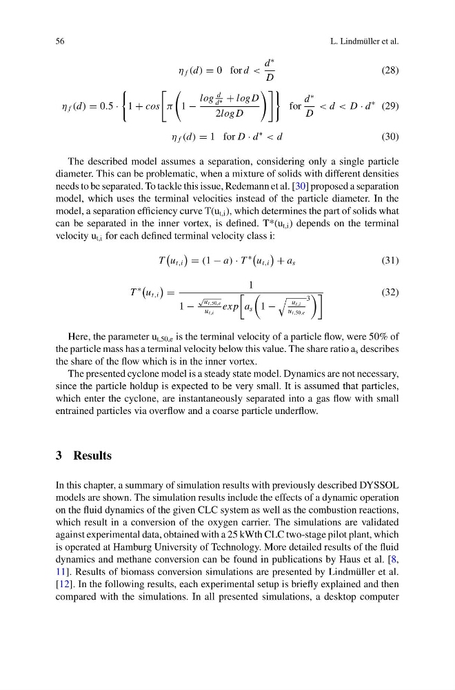
The described model assumes a separation, considering only a single particle
diameter. This can be problematic, when a mixture of solids with different densities
needs to be separated. To tackle this issue, Redemann et al. [30] proposed a separation
model, which uses the terminal velocities instead of the particle diameter. In the
model, a separation efficiency curve T(u t,i ), which determines the part of solids what
can be separated in the inner vortex, is defined. T*(u t,i ) depends on the terminal
velocity u t,i for each defined terminal velocity class i:
T
u t,i
= (1 − a) · T
∗
u t,i
+ a s
(31)
T
∗
u t,i
=
1
1 −
√
u t,50,e
u t,i
ex p
a s
1 −
u t,i
u t,50,e
3
(32)
Here, the parameter u t,50,e is the terminal velocity of a particle flow, were 50% of
the particle mass has a terminal velocity below this value. The share ratio a s describes
the share of the flow which is in the inner vortex.
The presented cyclone model is a steady state model. Dynamics are not necessary,
since the particle holdup is expected to be very small. It is assumed that particles,
which enter the cyclone, are instantaneously separated into a gas flow with small
entrained particles via overflow and a coarse particle underflow.
3 Results
In this chapter, a summary of simulation results with previously described DYSSOL
models are shown. The simulation results include the effects of a dynamic operation
on the fluid dynamics of the given CLC system as well as the combustion reactions,
which result in a conversion of the oxygen carrier. The simulations are validated
against experimental data, obtained with a 25 kWth CLC two-stage pilot plant, which
is operated at Hamburg University of Technology. More detailed results of the fluid
dynamics and methane conversion can be found in publications by Haus et al. [8,
11]. Results of biomass conversion simulations are presented by Lindmüller et al.
[12]. In the following results, each experimental setup is briefly explained and then
compared with the simulations. In all presented simulations, a desktop computer
L. Lindmüller et al.
η f (d) = 0 ford <
d
∗
D
(28)
η f (d) = 0.5 ·
1 + cos
π
1 −
log
d
d ∗ + log D
2log D
for
d
∗
D
< d < D · d
∗ (29)
η f (d) = 1 for D · d
∗
< d
(30)
The described model assumes a separation, considering only a single particle
diameter. This can be problematic, when a mixture of solids with different densities
needs to be separated. To tackle this issue, Redemann et al. [30] proposed a separation
model, which uses the terminal velocities instead of the particle diameter. In the
model, a separation efficiency curve T(u t,i ), which determines the part of solids what
can be separated in the inner vortex, is defined. T*(u t,i ) depends on the terminal
velocity u t,i for each defined terminal velocity class i:
T
u t,i
= (1 − a) · T
∗
u t,i
+ a s
(31)
T
∗
u t,i
=
1
1 −
√
u t,50,e
u t,i
ex p
a s
1 −
u t,i
u t,50,e
3
(32)
Here, the parameter u t,50,e is the terminal velocity of a particle flow, were 50% of
the particle mass has a terminal velocity below this value. The share ratio a s describes
the share of the flow which is in the inner vortex.
The presented cyclone model is a steady state model. Dynamics are not necessary,
since the particle holdup is expected to be very small. It is assumed that particles,
which enter the cyclone, are instantaneously separated into a gas flow with small
entrained particles via overflow and a coarse particle underflow.
3 Results
In this chapter, a summary of simulation results with previously described DYSSOL
models are shown. The simulation results include the effects of a dynamic operation
on the fluid dynamics of the given CLC system as well as the combustion reactions,
which result in a conversion of the oxygen carrier. The simulations are validated
against experimental data, obtained with a 25 kWth CLC two-stage pilot plant, which
is operated at Hamburg University of Technology. More detailed results of the fluid
dynamics and methane conversion can be found in publications by Haus et al. [8,
11]. Results of biomass conversion simulations are presented by Lindmüller et al.
[12]. In the following results, each experimental setup is briefly explained and then
compared with the simulations. In all presented simulations, a desktop computer