

2 Dynamic Modelling of Reactive Fluidized Bed Systems Using …
55
dm L S
dt
= ˙
m L S,in − ˙
m L S,out
(27)
2.3.3 Cyclone Unit
For gas-solid separation a cyclone model is implemented into DYSSOL. A system,
which is similar to the semi-empirical model by Muschelknautz [28], is implemented.
This model was validated against data from several hot units and is widely used for
cyclone design in Germany. In this work, the model was extended with an approach
by Klett et al. [29] to avoid errors in the population balances for fine particles.
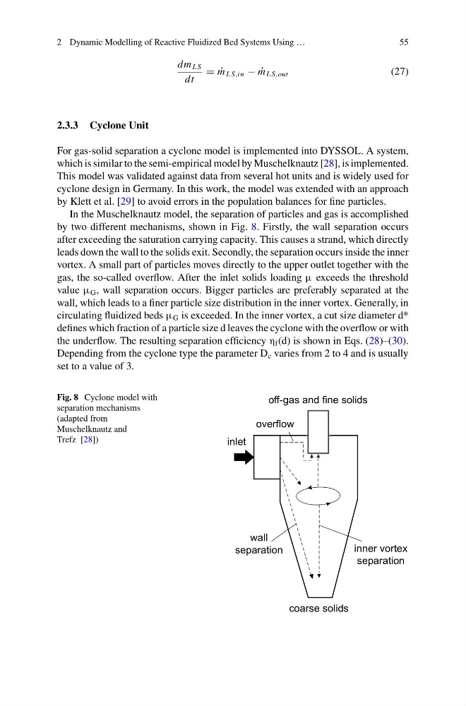
In the Muschelknautz model, the separation of particles and gas is accomplished
by two different mechanisms, shown in Fig. 8. Firstly, the wall separation occurs
after exceeding the saturation carrying capacity. This causes a strand, which directly
leads down the wall to the solids exit. Secondly, the separation occurs inside the inner
vortex. A small part of particles moves directly to the upper outlet together with the
gas, the so-called overflow. After the inlet solids loading μ exceeds the threshold
value μ G , wall separation occurs. Bigger particles are preferably separated at the
wall, which leads to a finer particle size distribution in the inner vortex. Generally, in
circulating fluidized beds μ G is exceeded. In the inner vortex, a cut size diameter d*
defines which fraction of a particle size d leaves the cyclone with the overflow or with
the underflow. The resulting separation efficiency η f (d) is shown in Eqs. (28)–(30).
Depending from the cyclone type the parameter D c varies from 2 to 4 and is usually
set to a value of 3.
Fig. 8 Cyclone model with
separation mechanisms
(adapted from
Muschelknautz and
Trefz [28])
inlet
off-gas and fine solids
coarse solids
inner vortex
separation
wall
separation
overflow
55
dm L S
dt
= ˙
m L S,in − ˙
m L S,out
(27)
2.3.3 Cyclone Unit
For gas-solid separation a cyclone model is implemented into DYSSOL. A system,
which is similar to the semi-empirical model by Muschelknautz [28], is implemented.
This model was validated against data from several hot units and is widely used for
cyclone design in Germany. In this work, the model was extended with an approach
by Klett et al. [29] to avoid errors in the population balances for fine particles.
In the Muschelknautz model, the separation of particles and gas is accomplished
by two different mechanisms, shown in Fig. 8. Firstly, the wall separation occurs
after exceeding the saturation carrying capacity. This causes a strand, which directly
leads down the wall to the solids exit. Secondly, the separation occurs inside the inner
vortex. A small part of particles moves directly to the upper outlet together with the
gas, the so-called overflow. After the inlet solids loading μ exceeds the threshold
value μ G , wall separation occurs. Bigger particles are preferably separated at the
wall, which leads to a finer particle size distribution in the inner vortex. Generally, in
circulating fluidized beds μ G is exceeded. In the inner vortex, a cut size diameter d*
defines which fraction of a particle size d leaves the cyclone with the overflow or with
the underflow. The resulting separation efficiency η f (d) is shown in Eqs. (28)–(30).
Depending from the cyclone type the parameter D c varies from 2 to 4 and is usually
set to a value of 3.
Fig. 8 Cyclone model with
separation mechanisms
(adapted from
Muschelknautz and
Trefz [28])
inlet
off-gas and fine solids
coarse solids
inner vortex
separation
wall
separation
overflow