

54
L. Lindmüller et al.
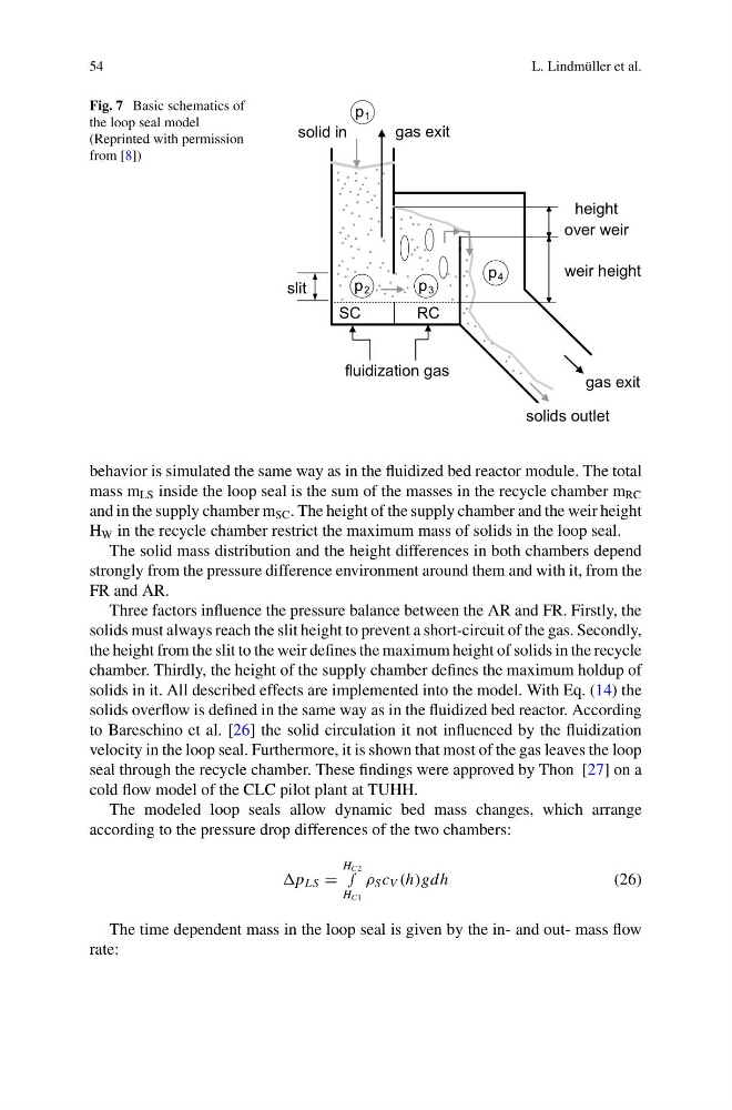
Fig. 7 Basic schematics of
the loop seal model
(Reprinted with permission
from [8])
fluidization gas
height
over weir
weir height
slit
p 1
p 2
p 3
p 4
SC
RC
solid in
solids outlet
gas exit
gas exit
behavior is simulated the same way as in the fluidized bed reactor module. The total
mass m LS inside the loop seal is the sum of the masses in the recycle chamber m RC
and in the supply chamber m SC . The height of the supply chamber and the weir height
H W in the recycle chamber restrict the maximum mass of solids in the loop seal.
The solid mass distribution and the height differences in both chambers depend
strongly from the pressure difference environment around them and with it, from the
FR and AR.
Three factors influence the pressure balance between the AR and FR. Firstly, the
solids must always reach the slit height to prevent a short-circuit of the gas. Secondly,
the height from the slit to the weir defines the maximum height of solids in the recycle
chamber. Thirdly, the height of the supply chamber defines the maximum holdup of
solids in it. All described effects are implemented into the model. With Eq. (14) the
solids overflow is defined in the same way as in the fluidized bed reactor. According
to Bareschino et al. [26] the solid circulation it not influenced by the fluidization
velocity in the loop seal. Furthermore, it is shown that most of the gas leaves the loop
seal through the recycle chamber. These findings were approved by Thon [27] on a
cold flow model of the CLC pilot plant at TUHH.
The modeled loop seals allow dynamic bed mass changes, which arrange
according to the pressure drop differences of the two chambers:
L S =
H C2
∫
H C1
ρ S c V (h)gdh
(26)
The time dependent mass in the loop seal is given by the in- and out- mass flow
rate:
L. Lindmüller et al.
Fig. 7 Basic schematics of
the loop seal model
(Reprinted with permission
from [8])
fluidization gas
height
over weir
weir height
slit
p 1
p 2
p 3
p 4
SC
RC
solid in
solids outlet
gas exit
gas exit
behavior is simulated the same way as in the fluidized bed reactor module. The total
mass m LS inside the loop seal is the sum of the masses in the recycle chamber m RC
and in the supply chamber m SC . The height of the supply chamber and the weir height
H W in the recycle chamber restrict the maximum mass of solids in the loop seal.
The solid mass distribution and the height differences in both chambers depend
strongly from the pressure difference environment around them and with it, from the
FR and AR.
Three factors influence the pressure balance between the AR and FR. Firstly, the
solids must always reach the slit height to prevent a short-circuit of the gas. Secondly,
the height from the slit to the weir defines the maximum height of solids in the recycle
chamber. Thirdly, the height of the supply chamber defines the maximum holdup of
solids in it. All described effects are implemented into the model. With Eq. (14) the
solids overflow is defined in the same way as in the fluidized bed reactor. According
to Bareschino et al. [26] the solid circulation it not influenced by the fluidization
velocity in the loop seal. Furthermore, it is shown that most of the gas leaves the loop
seal through the recycle chamber. These findings were approved by Thon [27] on a
cold flow model of the CLC pilot plant at TUHH.
The modeled loop seals allow dynamic bed mass changes, which arrange
according to the pressure drop differences of the two chambers:
L S =
H C2
∫
H C1
ρ S c V (h)gdh
(26)
The time dependent mass in the loop seal is given by the in- and out- mass flow
rate: