

440
S. Schiele et al.
known, exact measure of their roundness and mean width (grey line in Fig. 2). From
each body, multiple 2D projections Π p were generated and blur was added to the
images, as described in [9] (see Fig. 3 middle and right-hand side). Finally, two additive roundness parameters were calculated for each particle from its 2D projections
with the sharp and blurred 2D images (black lines in Fig. 2). The additive roundness
estimates the roundness parameter of the real 3D particle from its n proj projections:
μ
B
≈ 1 −
μ
mw
−
p
1
n proj
λ r,Π p
μ mw
(11)
In the following, it is described how μ
mw and λ r,Π p were obtained from n proj
projections of a particle in order to be able to calculate the roundness μ
B according
to Eq. (11). The first step was to find a 2D H-representation of each individual
projection. It was found by Hough transform [19] performed as follows. First, the
center of mass of a projection was determined and considered as the center of a
Cartesian coordinate system. Lines on the border of a projection can be described
by an angle ϕ and distance from the center of mass ρ. The vector (cos ϕ, sin ϕ)
T
describes a normal vector of such a line. Then any point on the line x is described
by the scalar product
ρ =
x,
cos ϕ
sin ϕ
(12)
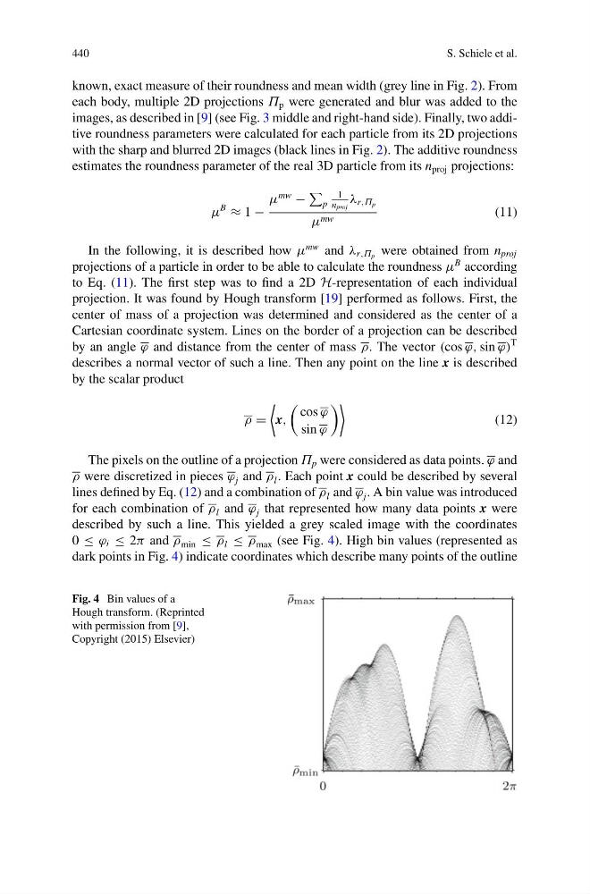
The pixels on the outline of a projection Π p were considered as data points. ϕ and
ρ were discretized in pieces ϕ j and ρ l . Each point x could be described by several
lines defined by Eq. (12) and a combination of ρ l and ϕ j . A bin value was introduced
for each combination of ρ l and ϕ j that represented how many data points x were
described by such a line. This yielded a grey scaled image with the coordinates
0 ≤ ϕ i ≤ 2π and ρ min ≤ ρ l ≤ ρ max (see Fig. 4). High bin values (represented as
dark points in Fig. 4) indicate coordinates which describe many points of the outline
Fig. 4 Bin values of a
Hough transform. (Reprinted
with permission from [9],
Copyright (2015) Elsevier)
S. Schiele et al.
known, exact measure of their roundness and mean width (grey line in Fig. 2). From
each body, multiple 2D projections Π p were generated and blur was added to the
images, as described in [9] (see Fig. 3 middle and right-hand side). Finally, two additive roundness parameters were calculated for each particle from its 2D projections
with the sharp and blurred 2D images (black lines in Fig. 2). The additive roundness
estimates the roundness parameter of the real 3D particle from its n proj projections:
μ
B
≈ 1 −
μ
mw
−
p
1
n proj
λ r,Π p
μ mw
(11)
In the following, it is described how μ
mw and λ r,Π p were obtained from n proj
projections of a particle in order to be able to calculate the roundness μ
B according
to Eq. (11). The first step was to find a 2D H-representation of each individual
projection. It was found by Hough transform [19] performed as follows. First, the
center of mass of a projection was determined and considered as the center of a
Cartesian coordinate system. Lines on the border of a projection can be described
by an angle ϕ and distance from the center of mass ρ. The vector (cos ϕ, sin ϕ)
T
describes a normal vector of such a line. Then any point on the line x is described
by the scalar product
ρ =
x,
cos ϕ
sin ϕ
(12)
The pixels on the outline of a projection Π p were considered as data points. ϕ and
ρ were discretized in pieces ϕ j and ρ l . Each point x could be described by several
lines defined by Eq. (12) and a combination of ρ l and ϕ j . A bin value was introduced
for each combination of ρ l and ϕ j that represented how many data points x were
described by such a line. This yielded a grey scaled image with the coordinates
0 ≤ ϕ i ≤ 2π and ρ min ≤ ρ l ≤ ρ max (see Fig. 4). High bin values (represented as
dark points in Fig. 4) indicate coordinates which describe many points of the outline
Fig. 4 Bin values of a
Hough transform. (Reprinted
with permission from [9],
Copyright (2015) Elsevier)