

13 Morphological Modelling and Simulation …
439
2.1 Description of Crystal Projections and Roundness
Measurement
A fundamental question in crystal or particle representation is, how to deal with
roundness instead of sharp edges and corners. A framework in this respect was
introduced by Reinhold et al. [9]. The roundness of a crystal can be used as a parameter
that describes how much attrition occurs in a process. To achieve this, first 3D crystals
were modeled and then projections of these models were generated. They were used
to validate the experimental procedures that are described in the end of this section.
The comparison of the exact roundness obtained from 3D models and the roundness
obtained from 2D projections of the model crystals allowed an evaluation of how
well the roundness can be measured when only 2D information is available and how
non-ideal images affect the roundness measurement. This is particularly interesting
because it is currently not possible to obtain 3D images of crystals in real time and
on-line analysis of particulate systems is often done by 2D image analysis.
To define the roundness of a particle, several definitions exist in the literature [15–
18]. Here, a new descriptor for roundness μ
B was defined so that it can be calculated
from the geometric properties of the Minkowski addition [9]. A spherical crystal
which is by definition perfectly round, can be described by Eq. (5) with h k = 0
and hence μ
mw
= 2λ r results from Eq. (8). A crystal that has sharp edges and is
therefore as little round as possible for a given kernel crystal, is described by Eq. (5)
with λ r = 0 and hence μ
mw
= μ
mw
k results from Eq. (8). To reflect this concept of
roundness the roundness parameter μ
B is written as
μ
B
= 1 −
μ
mw
k
μ mw =
2λ r
μ
mw
k + 2λ r
(10)
Note that it can be calculated for a body of any dimension, in this case for 2D and
3D bodies equivalently.
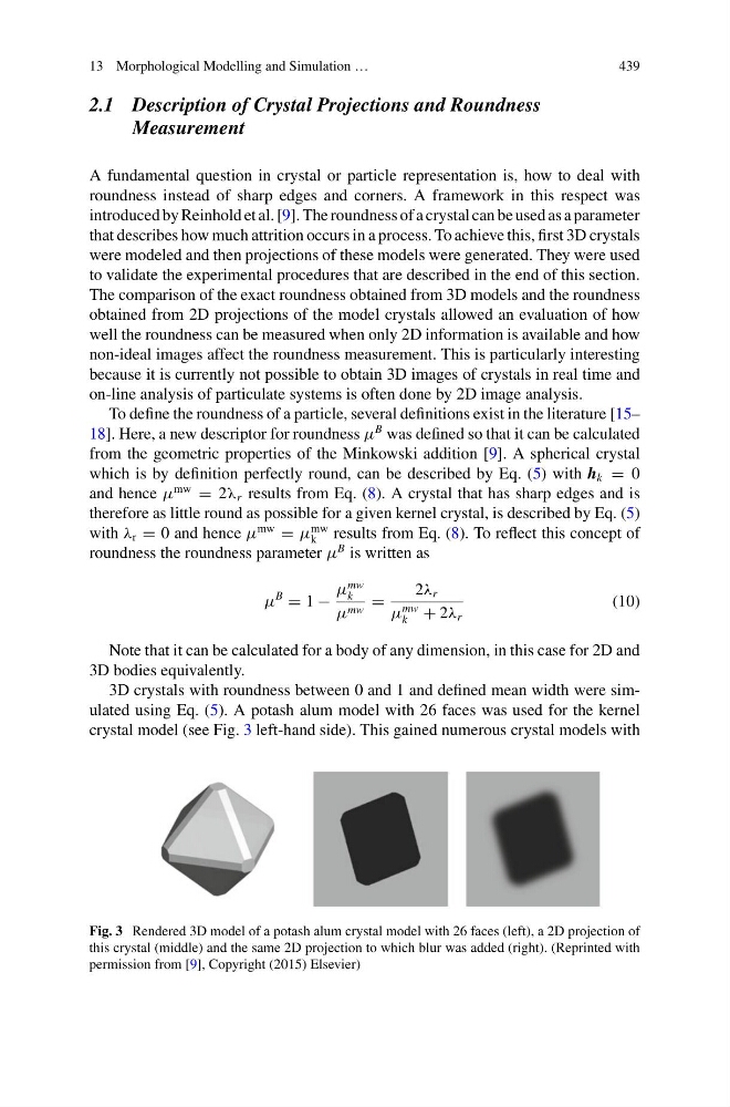
3D crystals with roundness between 0 and 1 and defined mean width were simulated using Eq. (5). A potash alum model with 26 faces was used for the kernel
crystal model (see Fig. 3 left-hand side). This gained numerous crystal models with
Fig. 3 Rendered 3D model of a potash alum crystal model with 26 faces (left), a 2D projection of
this crystal (middle) and the same 2D projection to which blur was added (right). (Reprinted with
permission from [9], Copyright (2015) Elsevier)
439
2.1 Description of Crystal Projections and Roundness
Measurement
A fundamental question in crystal or particle representation is, how to deal with
roundness instead of sharp edges and corners. A framework in this respect was
introduced by Reinhold et al. [9]. The roundness of a crystal can be used as a parameter
that describes how much attrition occurs in a process. To achieve this, first 3D crystals
were modeled and then projections of these models were generated. They were used
to validate the experimental procedures that are described in the end of this section.
The comparison of the exact roundness obtained from 3D models and the roundness
obtained from 2D projections of the model crystals allowed an evaluation of how
well the roundness can be measured when only 2D information is available and how
non-ideal images affect the roundness measurement. This is particularly interesting
because it is currently not possible to obtain 3D images of crystals in real time and
on-line analysis of particulate systems is often done by 2D image analysis.
To define the roundness of a particle, several definitions exist in the literature [15–
18]. Here, a new descriptor for roundness μ
B was defined so that it can be calculated
from the geometric properties of the Minkowski addition [9]. A spherical crystal
which is by definition perfectly round, can be described by Eq. (5) with h k = 0
and hence μ
mw
= 2λ r results from Eq. (8). A crystal that has sharp edges and is
therefore as little round as possible for a given kernel crystal, is described by Eq. (5)
with λ r = 0 and hence μ
mw
= μ
mw
k results from Eq. (8). To reflect this concept of
roundness the roundness parameter μ
B is written as
μ
B
= 1 −
μ
mw
k
μ mw =
2λ r
μ
mw
k + 2λ r
(10)
Note that it can be calculated for a body of any dimension, in this case for 2D and
3D bodies equivalently.
3D crystals with roundness between 0 and 1 and defined mean width were simulated using Eq. (5). A potash alum model with 26 faces was used for the kernel
crystal model (see Fig. 3 left-hand side). This gained numerous crystal models with
Fig. 3 Rendered 3D model of a potash alum crystal model with 26 faces (left), a 2D projection of
this crystal (middle) and the same 2D projection to which blur was added (right). (Reprinted with
permission from [9], Copyright (2015) Elsevier)