

376
M. Weers et al.
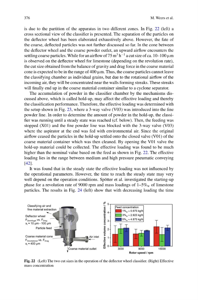
is due to the partition of the apparatus in two different zones. In Fig. 22 (left) a
cross sectional view of the classifier is presented. The separation of the particles on
the deflector wheel has been elaborated exhaustively above. However, the fate of
the coarse, deflected particles was not further discussed so far. In the cone between
the deflector wheel and the coarse powder outlet, an upward airflow encounters the
settling coarse particles. While for an airflow of 75 m
3 h
−1 a cut size of ca. 10–100 μm
is observed on the deflector wheel for limestone (depending on the revolution rate),
the cut size obtained from the balance of gravity and drag force in the coarse material
cone is expected to be in the range of 400 μm. Thus, the coarse particles cannot leave
the classifying chamber as individual grains, but due to the rotational airflow of the
incoming air, they will be concentrated near the walls forming streaks. These streaks
will finally end up in the coarse material container similar to a cyclone separator.
The accumulation of powder in the classifier chamber by the mechanisms discussed above, which is called hold-up, may affect the effective loading and thereby
the classification performance. Therefore, the effective loading was determined with
the setup shown in Fig. 23, where a 3-way valve (V03) was introduced into the fine
powder line. In order to determine the amount of powder in the hold-up, the classifier was running until a steady state was reached (cf. below). Then, the feeding was
stopped (X01) and the fine powder line was blocked with the 3-way valve (V03)
where the aspirator at the end was fed with environmental air. Since the original
airflow ceased the particles in the hold-up settled onto the closed valve (V01) of the
coarse material container which was then cleaned. By opening the V01 valve the
hold-up material could be collected. The effective loading was found to be much
higher than the nominal value based on the feed as shown in Fig. 22. The effective
loading lies in the range between medium and high pressure pneumatic conveying
[42].
It was found that in the steady state the effective loading was not influenced by
the operational parameters. However, the time to reach the steady state may very
well depend on the operation conditions. Spötter et al. investigated the starting-up
phase for a revolution rate of 9000 rpm and mass loadings of 1–5% w of limestone
particles. The results in Fig. 24 (left) show that with decreasing loading the time
Fig. 22 (Left) The two cut sizes in the operation of the deflector wheel classifier. (Right) Effective
mass concentration
M. Weers et al.
is due to the partition of the apparatus in two different zones. In Fig. 22 (left) a
cross sectional view of the classifier is presented. The separation of the particles on
the deflector wheel has been elaborated exhaustively above. However, the fate of
the coarse, deflected particles was not further discussed so far. In the cone between
the deflector wheel and the coarse powder outlet, an upward airflow encounters the
settling coarse particles. While for an airflow of 75 m
3 h
−1 a cut size of ca. 10–100 μm
is observed on the deflector wheel for limestone (depending on the revolution rate),
the cut size obtained from the balance of gravity and drag force in the coarse material
cone is expected to be in the range of 400 μm. Thus, the coarse particles cannot leave
the classifying chamber as individual grains, but due to the rotational airflow of the
incoming air, they will be concentrated near the walls forming streaks. These streaks
will finally end up in the coarse material container similar to a cyclone separator.
The accumulation of powder in the classifier chamber by the mechanisms discussed above, which is called hold-up, may affect the effective loading and thereby
the classification performance. Therefore, the effective loading was determined with
the setup shown in Fig. 23, where a 3-way valve (V03) was introduced into the fine
powder line. In order to determine the amount of powder in the hold-up, the classifier was running until a steady state was reached (cf. below). Then, the feeding was
stopped (X01) and the fine powder line was blocked with the 3-way valve (V03)
where the aspirator at the end was fed with environmental air. Since the original
airflow ceased the particles in the hold-up settled onto the closed valve (V01) of the
coarse material container which was then cleaned. By opening the V01 valve the
hold-up material could be collected. The effective loading was found to be much
higher than the nominal value based on the feed as shown in Fig. 22. The effective
loading lies in the range between medium and high pressure pneumatic conveying
[42].
It was found that in the steady state the effective loading was not influenced by
the operational parameters. However, the time to reach the steady state may very
well depend on the operation conditions. Spötter et al. investigated the starting-up
phase for a revolution rate of 9000 rpm and mass loadings of 1–5% w of limestone
particles. The results in Fig. 24 (left) show that with decreasing loading the time
Fig. 22 (Left) The two cut sizes in the operation of the deflector wheel classifier. (Right) Effective
mass concentration