

10 Dynamics of Separation Characteristics of Sieving and Flow …
369
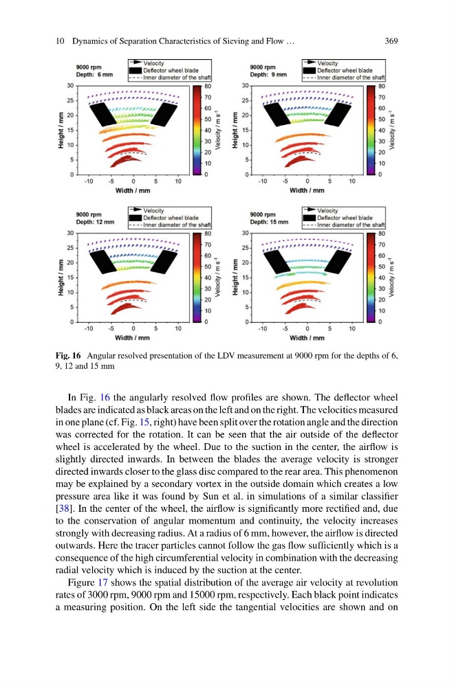
Fig. 16 Angular resolved presentation of the LDV measurement at 9000 rpm for the depths of 6,
9, 12 and 15 mm
In Fig. 16 the angularly resolved flow profiles are shown. The deflector wheel
blades are indicated as black areas on the left and on the right. The velocities measured
in one plane (cf. Fig. 15, right) have been split over the rotation angle and the direction
was corrected for the rotation. It can be seen that the air outside of the deflector
wheel is accelerated by the wheel. Due to the suction in the center, the airflow is
slightly directed inwards. In between the blades the average velocity is stronger
directed inwards closer to the glass disc compared to the rear area. This phenomenon
may be explained by a secondary vortex in the outside domain which creates a low
pressure area like it was found by Sun et al. in simulations of a similar classifier
[38]. In the center of the wheel, the airflow is significantly more rectified and, due
to the conservation of angular momentum and continuity, the velocity increases
strongly with decreasing radius. At a radius of 6 mm, however, the airflow is directed
outwards. Here the tracer particles cannot follow the gas flow sufficiently which is a
consequence of the high circumferential velocity in combination with the decreasing
radial velocity which is induced by the suction at the center.
Figure 17 shows the spatial distribution of the average air velocity at revolution
rates of 3000 rpm, 9000 rpm and 15000 rpm, respectively. Each black point indicates
a measuring position. On the left side the tangential velocities are shown and on
369
Fig. 16 Angular resolved presentation of the LDV measurement at 9000 rpm for the depths of 6,
9, 12 and 15 mm
In Fig. 16 the angularly resolved flow profiles are shown. The deflector wheel
blades are indicated as black areas on the left and on the right. The velocities measured
in one plane (cf. Fig. 15, right) have been split over the rotation angle and the direction
was corrected for the rotation. It can be seen that the air outside of the deflector
wheel is accelerated by the wheel. Due to the suction in the center, the airflow is
slightly directed inwards. In between the blades the average velocity is stronger
directed inwards closer to the glass disc compared to the rear area. This phenomenon
may be explained by a secondary vortex in the outside domain which creates a low
pressure area like it was found by Sun et al. in simulations of a similar classifier
[38]. In the center of the wheel, the airflow is significantly more rectified and, due
to the conservation of angular momentum and continuity, the velocity increases
strongly with decreasing radius. At a radius of 6 mm, however, the airflow is directed
outwards. Here the tracer particles cannot follow the gas flow sufficiently which is a
consequence of the high circumferential velocity in combination with the decreasing
radial velocity which is induced by the suction at the center.
Figure 17 shows the spatial distribution of the average air velocity at revolution
rates of 3000 rpm, 9000 rpm and 15000 rpm, respectively. Each black point indicates
a measuring position. On the left side the tangential velocities are shown and on