

354
M. Weers et al.
blades v rad , where v rad = ˙
V/(h U eff ) where ˙
V is the carrier gas volume flow rate, U eff
is the open circumferential length and h is the height of the openings:
x t = 18 η eff τ
∗
/ρ p
(4)
where τ* is obtained by solving the quadratic equation:
τ
∗2
((COR v 0 )
2
/R) + τ
∗
(v r + 2 H(COR v 0 )
2
/v 0 )−(H
2
(COR v 0 )
2
/v
2
0 ) = 0 (5)
Finally, the distance H could be measured in an idealized experiment where particles are shot against an immobile target wall and observed with a high speed camera
(cf. [17]) or derived from DEM simulations together with values for the COR [17,
19]. However, for dense particle clouds within the rapidly rotating blades of the
deflector wheel, it is very challenging to observe the distance H. Therefore, direct
measurements of the particle velocities before and after impact on the blades were
performed using high speed camera at low concentrations (cf. Sect. 2.4). Also, the
particle trajectories were recorded and the particle impaction area on the blades was
derived.
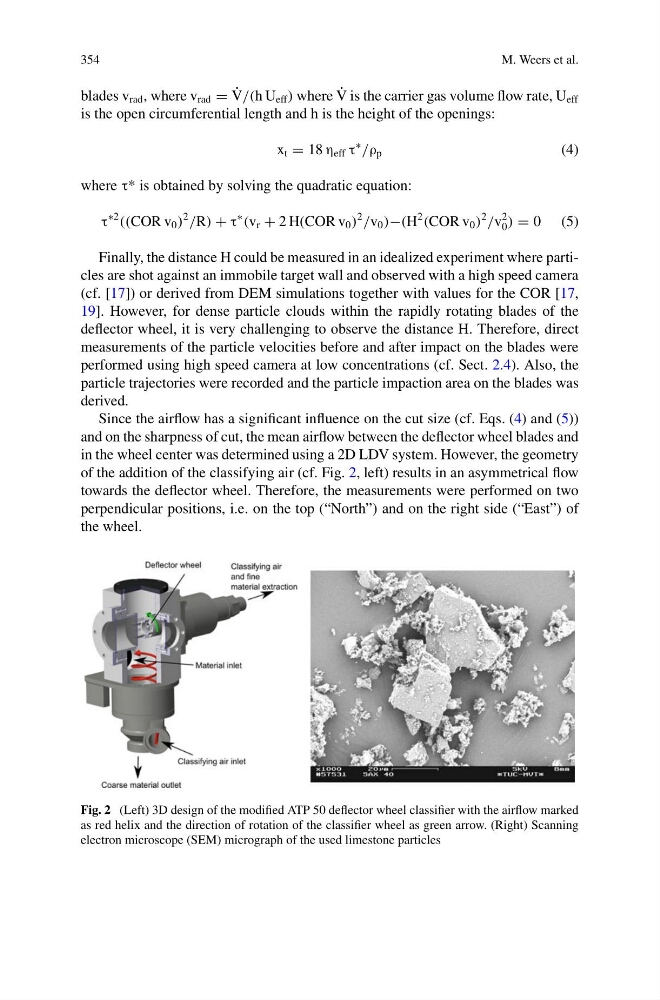
Since the airflow has a significant influence on the cut size (cf. Eqs. (4) and (5))
and on the sharpness of cut, the mean airflow between the deflector wheel blades and
in the wheel center was determined using a 2D LDV system. However, the geometry
of the addition of the classifying air (cf. Fig. 2, left) results in an asymmetrical flow
towards the deflector wheel. Therefore, the measurements were performed on two
perpendicular positions, i.e. on the top (“North”) and on the right side (“East”) of
the wheel.
Fig. 2 (Left) 3D design of the modified ATP 50 deflector wheel classifier with the airflow marked
as red helix and the direction of rotation of the classifier wheel as green arrow. (Right) Scanning
electron microscope (SEM) micrograph of the used limestone particles
M. Weers et al.
blades v rad , where v rad = ˙
V/(h U eff ) where ˙
V is the carrier gas volume flow rate, U eff
is the open circumferential length and h is the height of the openings:
x t = 18 η eff τ
∗
/ρ p
(4)
where τ* is obtained by solving the quadratic equation:
τ
∗2
((COR v 0 )
2
/R) + τ
∗
(v r + 2 H(COR v 0 )
2
/v 0 )−(H
2
(COR v 0 )
2
/v
2
0 ) = 0 (5)
Finally, the distance H could be measured in an idealized experiment where particles are shot against an immobile target wall and observed with a high speed camera
(cf. [17]) or derived from DEM simulations together with values for the COR [17,
19]. However, for dense particle clouds within the rapidly rotating blades of the
deflector wheel, it is very challenging to observe the distance H. Therefore, direct
measurements of the particle velocities before and after impact on the blades were
performed using high speed camera at low concentrations (cf. Sect. 2.4). Also, the
particle trajectories were recorded and the particle impaction area on the blades was
derived.
Since the airflow has a significant influence on the cut size (cf. Eqs. (4) and (5))
and on the sharpness of cut, the mean airflow between the deflector wheel blades and
in the wheel center was determined using a 2D LDV system. However, the geometry
of the addition of the classifying air (cf. Fig. 2, left) results in an asymmetrical flow
towards the deflector wheel. Therefore, the measurements were performed on two
perpendicular positions, i.e. on the top (“North”) and on the right side (“East”) of
the wheel.
Fig. 2 (Left) 3D design of the modified ATP 50 deflector wheel classifier with the airflow marked
as red helix and the direction of rotation of the classifier wheel as green arrow. (Right) Scanning
electron microscope (SEM) micrograph of the used limestone particles