

254
M. Gleiss and H. Nirschl
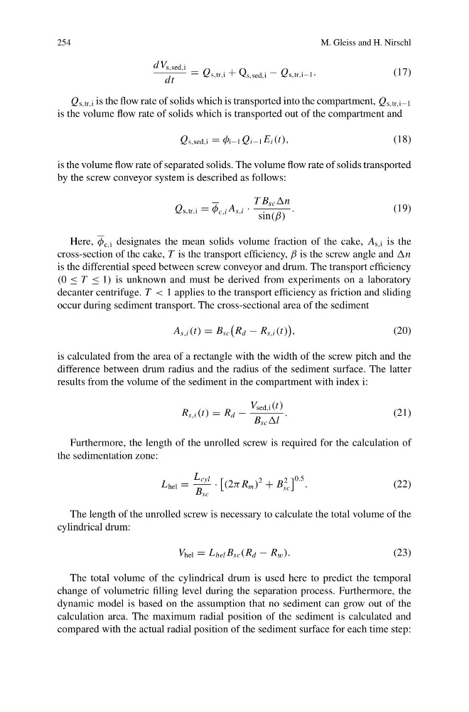
dV s,sed,i
dt
= Q s,tr,i + Q s,sed,i − Q s,tr,i−1 .
(17)
Q s,tr,i is the flow rate of solids which is transported into the compartment, Q s,tr,i−1
is the volume flow rate of solids which is transported out of the compartment and
Q s,sed,i = φ i−1 Q i−1 E i (t),
(18)
is the volume flow rate of separated solids. The volume flow rate of solids transported
by the screw conveyor system is described as follows:
Q s,tr,i = φ c,i A s,i ·
T B sc n
sin(β)
.
(19)
Here, φ c,i designates the mean solids volume fraction of the cake, A s,i is the
cross-section of the cake, T is the transport efficiency, β is the screw angle and n
is the differential speed between screw conveyor and drum. The transport efficiency
(0 ≤ T ≤ 1) is unknown and must be derived from experiments on a laboratory
decanter centrifuge. T < 1 applies to the transport efficiency as friction and sliding
occur during sediment transport. The cross-sectional area of the sediment
A s,i (t) = B sc
R d − R s,i (t)
,
(20)
is calculated from the area of a rectangle with the width of the screw pitch and the
difference between drum radius and the radius of the sediment surface. The latter
results from the volume of the sediment in the compartment with index i:
R s,i (t) = R d −
V sed,i (t)
B sc l
.
(21)
Furthermore, the length of the unrolled screw is required for the calculation of
the sedimentation zone:
L hel =
L cyl
B sc
·
(2π R m )
2
+ B
2
sc
0.5 .
(22)
The length of the unrolled screw is necessary to calculate the total volume of the
cylindrical drum:
V hel = L hel B sc (R d − R w ).
(23)
The total volume of the cylindrical drum is used here to predict the temporal
change of volumetric filling level during the separation process. Furthermore, the
dynamic model is based on the assumption that no sediment can grow out of the
calculation area. The maximum radial position of the sediment is calculated and
compared with the actual radial position of the sediment surface for each time step:
M. Gleiss and H. Nirschl
dV s,sed,i
dt
= Q s,tr,i + Q s,sed,i − Q s,tr,i−1 .
(17)
Q s,tr,i is the flow rate of solids which is transported into the compartment, Q s,tr,i−1
is the volume flow rate of solids which is transported out of the compartment and
Q s,sed,i = φ i−1 Q i−1 E i (t),
(18)
is the volume flow rate of separated solids. The volume flow rate of solids transported
by the screw conveyor system is described as follows:
Q s,tr,i = φ c,i A s,i ·
T B sc n
sin(β)
.
(19)
Here, φ c,i designates the mean solids volume fraction of the cake, A s,i is the
cross-section of the cake, T is the transport efficiency, β is the screw angle and n
is the differential speed between screw conveyor and drum. The transport efficiency
(0 ≤ T ≤ 1) is unknown and must be derived from experiments on a laboratory
decanter centrifuge. T < 1 applies to the transport efficiency as friction and sliding
occur during sediment transport. The cross-sectional area of the sediment
A s,i (t) = B sc
R d − R s,i (t)
,
(20)
is calculated from the area of a rectangle with the width of the screw pitch and the
difference between drum radius and the radius of the sediment surface. The latter
results from the volume of the sediment in the compartment with index i:
R s,i (t) = R d −
V sed,i (t)
B sc l
.
(21)
Furthermore, the length of the unrolled screw is required for the calculation of
the sedimentation zone:
L hel =
L cyl
B sc
·
(2π R m )
2
+ B
2
sc
0.5 .
(22)
The length of the unrolled screw is necessary to calculate the total volume of the
cylindrical drum:
V hel = L hel B sc (R d − R w ).
(23)
The total volume of the cylindrical drum is used here to predict the temporal
change of volumetric filling level during the separation process. Furthermore, the
dynamic model is based on the assumption that no sediment can grow out of the
calculation area. The maximum radial position of the sediment is calculated and
compared with the actual radial position of the sediment surface for each time step: