

7 Dynamic Simulation of Mechanical Fluid Separation in Solid …
253
q 3,i (x, t) = q 3,i−1 (x, t)
(1 − G i (x, t))
(1 − E i (t))
.
(13)
The unknown variables of the presented equations are the grade efficiency and
the volume of a compartment (index i). For decanter centrifuges, the grade efficiency depends on the material properties, the centrifuge geometry and the process
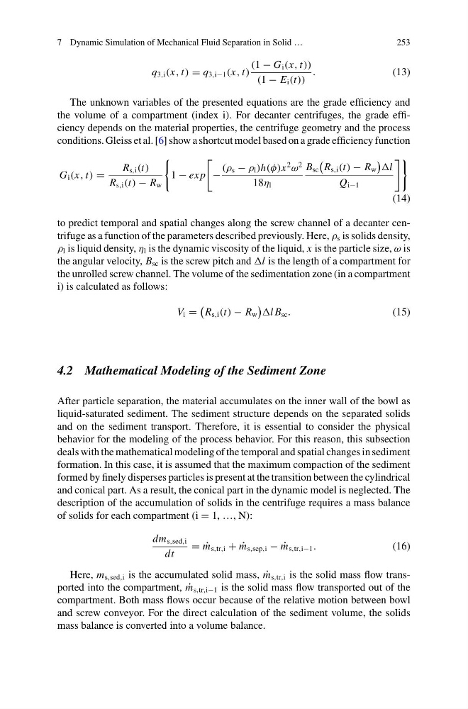
conditions. Gleiss et al. [6] show a shortcut model based on a grade efficiency function
G i (x, t) =
R s,i (t)
R s,i (t) − R w
1 − ex p
−
(ρ s − ρ l )h(φ)x
2
ω
2
18η l
B sc
R s,i (t) − R w
l
Q i−1
(14)
to predict temporal and spatial changes along the screw channel of a decanter centrifuge as a function of the parameters described previously. Here, ρ s is solids density,
ρ l is liquid density, η l is the dynamic viscosity of the liquid, x is the particle size, ω is
the angular velocity, B sc is the screw pitch and l is the length of a compartment for
the unrolled screw channel. The volume of the sedimentation zone (in a compartment
i) is calculated as follows:
V i =
R s,i (t) − R w
l B sc .
(15)
4.2 Mathematical Modeling of the Sediment Zone
After particle separation, the material accumulates on the inner wall of the bowl as
liquid-saturated sediment. The sediment structure depends on the separated solids
and on the sediment transport. Therefore, it is essential to consider the physical
behavior for the modeling of the process behavior. For this reason, this subsection
deals with the mathematical modeling of the temporal and spatial changes in sediment
formation. In this case, it is assumed that the maximum compaction of the sediment
formed by finely disperses particles is present at the transition between the cylindrical
and conical part. As a result, the conical part in the dynamic model is neglected. The
description of the accumulation of solids in the centrifuge requires a mass balance
of solids for each compartment (i = 1, …, N):
dm s,sed,i
dt
= ˙
m s,tr,i + ˙
m s,sep,i − ˙
m s,tr,i−1 .
(16)
Here, m s,sed,i is the accumulated solid mass, ˙
m s,tr,i is the solid mass flow transported into the compartment, ˙
m s,tr,i−1 is the solid mass flow transported out of the
compartment. Both mass flows occur because of the relative motion between bowl
and screw conveyor. For the direct calculation of the sediment volume, the solids
mass balance is converted into a volume balance.
253
q 3,i (x, t) = q 3,i−1 (x, t)
(1 − G i (x, t))
(1 − E i (t))
.
(13)
The unknown variables of the presented equations are the grade efficiency and
the volume of a compartment (index i). For decanter centrifuges, the grade efficiency depends on the material properties, the centrifuge geometry and the process
conditions. Gleiss et al. [6] show a shortcut model based on a grade efficiency function
G i (x, t) =
R s,i (t)
R s,i (t) − R w
1 − ex p
−
(ρ s − ρ l )h(φ)x
2
ω
2
18η l
B sc
R s,i (t) − R w
l
Q i−1
(14)
to predict temporal and spatial changes along the screw channel of a decanter centrifuge as a function of the parameters described previously. Here, ρ s is solids density,
ρ l is liquid density, η l is the dynamic viscosity of the liquid, x is the particle size, ω is
the angular velocity, B sc is the screw pitch and l is the length of a compartment for
the unrolled screw channel. The volume of the sedimentation zone (in a compartment
i) is calculated as follows:
V i =
R s,i (t) − R w
l B sc .
(15)
4.2 Mathematical Modeling of the Sediment Zone
After particle separation, the material accumulates on the inner wall of the bowl as
liquid-saturated sediment. The sediment structure depends on the separated solids
and on the sediment transport. Therefore, it is essential to consider the physical
behavior for the modeling of the process behavior. For this reason, this subsection
deals with the mathematical modeling of the temporal and spatial changes in sediment
formation. In this case, it is assumed that the maximum compaction of the sediment
formed by finely disperses particles is present at the transition between the cylindrical
and conical part. As a result, the conical part in the dynamic model is neglected. The
description of the accumulation of solids in the centrifuge requires a mass balance
of solids for each compartment (i = 1, …, N):
dm s,sed,i
dt
= ˙
m s,tr,i + ˙
m s,sep,i − ˙
m s,tr,i−1 .
(16)
Here, m s,sed,i is the accumulated solid mass, ˙
m s,tr,i is the solid mass flow transported into the compartment, ˙
m s,tr,i−1 is the solid mass flow transported out of the
compartment. Both mass flows occur because of the relative motion between bowl
and screw conveyor. For the direct calculation of the sediment volume, the solids
mass balance is converted into a volume balance.