

7 Dynamic Simulation of Mechanical Fluid Separation in Solid …
249
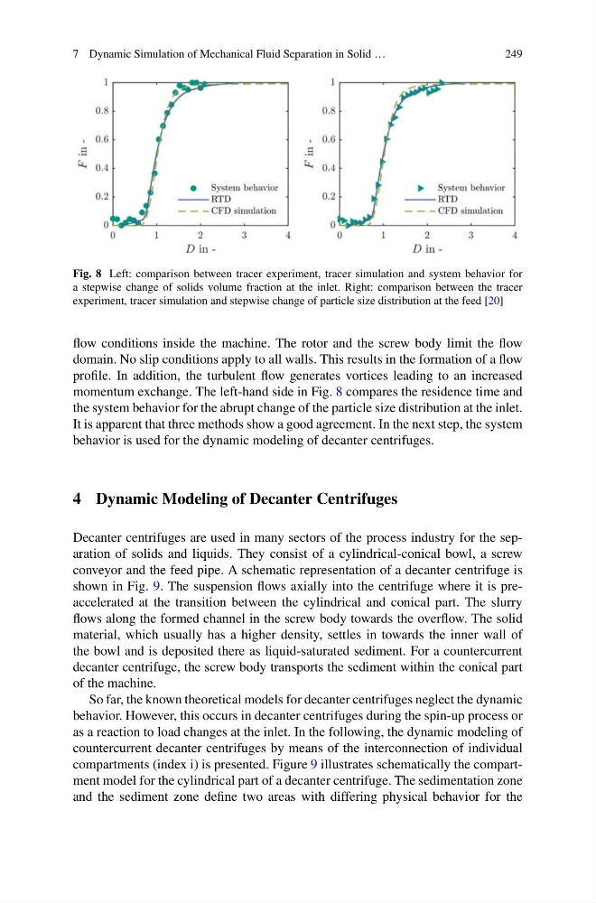
Fig. 8 Left: comparison between tracer experiment, tracer simulation and system behavior for
a stepwise change of solids volume fraction at the inlet. Right: comparison between the tracer
experiment, tracer simulation and stepwise change of particle size distribution at the feed [20]
flow conditions inside the machine. The rotor and the screw body limit the flow
domain. No slip conditions apply to all walls. This results in the formation of a flow
profile. In addition, the turbulent flow generates vortices leading to an increased
momentum exchange. The left-hand side in Fig. 8 compares the residence time and
the system behavior for the abrupt change of the particle size distribution at the inlet.
It is apparent that three methods show a good agreement. In the next step, the system
behavior is used for the dynamic modeling of decanter centrifuges.
4 Dynamic Modeling of Decanter Centrifuges
Decanter centrifuges are used in many sectors of the process industry for the separation of solids and liquids. They consist of a cylindrical-conical bowl, a screw
conveyor and the feed pipe. A schematic representation of a decanter centrifuge is
shown in Fig. 9. The suspension flows axially into the centrifuge where it is preaccelerated at the transition between the cylindrical and conical part. The slurry
flows along the formed channel in the screw body towards the overflow. The solid
material, which usually has a higher density, settles in towards the inner wall of
the bowl and is deposited there as liquid-saturated sediment. For a countercurrent
decanter centrifuge, the screw body transports the sediment within the conical part
of the machine.
So far, the known theoretical models for decanter centrifuges neglect the dynamic
behavior. However, this occurs in decanter centrifuges during the spin-up process or
as a reaction to load changes at the inlet. In the following, the dynamic modeling of
countercurrent decanter centrifuges by means of the interconnection of individual
compartments (index i) is presented. Figure 9 illustrates schematically the compartment model for the cylindrical part of a decanter centrifuge. The sedimentation zone
and the sediment zone define two areas with differing physical behavior for the
249
Fig. 8 Left: comparison between tracer experiment, tracer simulation and system behavior for
a stepwise change of solids volume fraction at the inlet. Right: comparison between the tracer
experiment, tracer simulation and stepwise change of particle size distribution at the feed [20]
flow conditions inside the machine. The rotor and the screw body limit the flow
domain. No slip conditions apply to all walls. This results in the formation of a flow
profile. In addition, the turbulent flow generates vortices leading to an increased
momentum exchange. The left-hand side in Fig. 8 compares the residence time and
the system behavior for the abrupt change of the particle size distribution at the inlet.
It is apparent that three methods show a good agreement. In the next step, the system
behavior is used for the dynamic modeling of decanter centrifuges.
4 Dynamic Modeling of Decanter Centrifuges
Decanter centrifuges are used in many sectors of the process industry for the separation of solids and liquids. They consist of a cylindrical-conical bowl, a screw
conveyor and the feed pipe. A schematic representation of a decanter centrifuge is
shown in Fig. 9. The suspension flows axially into the centrifuge where it is preaccelerated at the transition between the cylindrical and conical part. The slurry
flows along the formed channel in the screw body towards the overflow. The solid
material, which usually has a higher density, settles in towards the inner wall of
the bowl and is deposited there as liquid-saturated sediment. For a countercurrent
decanter centrifuge, the screw body transports the sediment within the conical part
of the machine.
So far, the known theoretical models for decanter centrifuges neglect the dynamic
behavior. However, this occurs in decanter centrifuges during the spin-up process or
as a reaction to load changes at the inlet. In the following, the dynamic modeling of
countercurrent decanter centrifuges by means of the interconnection of individual
compartments (index i) is presented. Figure 9 illustrates schematically the compartment model for the cylindrical part of a decanter centrifuge. The sedimentation zone
and the sediment zone define two areas with differing physical behavior for the