

248
M. Gleiss and H. Nirschl
The third method to determine the residence time behavior is based on CFD simulations in combination with a transport equation taking into account the dispersion of
a tracer by a passive scalar [27]. Modeling a passive scalar using a transport equation
requires that the tracer has the same physical properties as the fluid. Thus, there is
no cross-exchange due to a density difference.
The CFD simulations assume, that the screw rotates at the same speed as the bowl.
Thus, a SRF describes the influence of centrifugal and Coriolis force. Additionally,
a stationary flow is expected for the CFD simulations. Moreover, at the beginning
there is no tracer in the centrifuge (F = 0). The step change to F = 1 simulates the
injection of the tracer into the lab-scale decanter centrifuge. By specifying F = 1 at
the inlet, the residence time behavior results directly from the tracer concentration
at the overflow.
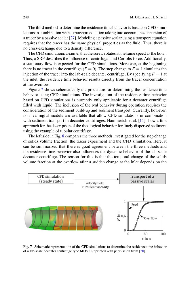
Figure 7 shows schematically the procedure for determining the residence time
behavior using CFD simulations. The investigation of the residence time behavior
based on CFD simulations is currently only applicable for a decanter centrifuge
filled with liquid. The inclusion of the real behavior during operation requires the
consideration of the sediment build-up and sediment transport. Currently, however,
no meaningful models are available that allow CFD simulations in combination
with sediment transport in decanter centrifuges. Hammerich et al. [11] show a first
approach for the description of the rheological behavior for finely dispersed sediment
using the example of tubular centrifuge.
The left side in Fig. 8 compares the three methods investigated for the step change
of solids volume fraction, the tracer experiment and the CFD simulation. Here, it
can be summarized that there is good agreement between the three methods and
the residence time behavior also influences the dynamic behavior of the lab-scale
decanter centrifuge. The reason for this is that the temporal change of the solids
volume fraction at the overflow after a sudden change at the inlet depends on the
Fig. 7 Schematic representation of the CFD simulations to determine the residence time behavior
of a lab-scale decanter centrifuge type MD80. Reprinted with permission from [20]
M. Gleiss and H. Nirschl
The third method to determine the residence time behavior is based on CFD simulations in combination with a transport equation taking into account the dispersion of
a tracer by a passive scalar [27]. Modeling a passive scalar using a transport equation
requires that the tracer has the same physical properties as the fluid. Thus, there is
no cross-exchange due to a density difference.
The CFD simulations assume, that the screw rotates at the same speed as the bowl.
Thus, a SRF describes the influence of centrifugal and Coriolis force. Additionally,
a stationary flow is expected for the CFD simulations. Moreover, at the beginning
there is no tracer in the centrifuge (F = 0). The step change to F = 1 simulates the
injection of the tracer into the lab-scale decanter centrifuge. By specifying F = 1 at
the inlet, the residence time behavior results directly from the tracer concentration
at the overflow.
Figure 7 shows schematically the procedure for determining the residence time
behavior using CFD simulations. The investigation of the residence time behavior
based on CFD simulations is currently only applicable for a decanter centrifuge
filled with liquid. The inclusion of the real behavior during operation requires the
consideration of the sediment build-up and sediment transport. Currently, however,
no meaningful models are available that allow CFD simulations in combination
with sediment transport in decanter centrifuges. Hammerich et al. [11] show a first
approach for the description of the rheological behavior for finely dispersed sediment
using the example of tubular centrifuge.
The left side in Fig. 8 compares the three methods investigated for the step change
of solids volume fraction, the tracer experiment and the CFD simulation. Here, it
can be summarized that there is good agreement between the three methods and
the residence time behavior also influences the dynamic behavior of the lab-scale
decanter centrifuge. The reason for this is that the temporal change of the solids
volume fraction at the overflow after a sudden change at the inlet depends on the
Fig. 7 Schematic representation of the CFD simulations to determine the residence time behavior
of a lab-scale decanter centrifuge type MD80. Reprinted with permission from [20]