

7 Dynamic Simulation of Mechanical Fluid Separation in Solid …
247
noted, that experimental residence time measurement only considers a machine filled
with liquid.
The second method is the determination of the system behavior for the same
lab-scale decanter centrifuge. Here, the particle size or the solids volume fraction is
changed at the inlet to investigate the response of the machine to the load change
applied. The third method applies CFD simulations in combination with a passive
tracer transport.
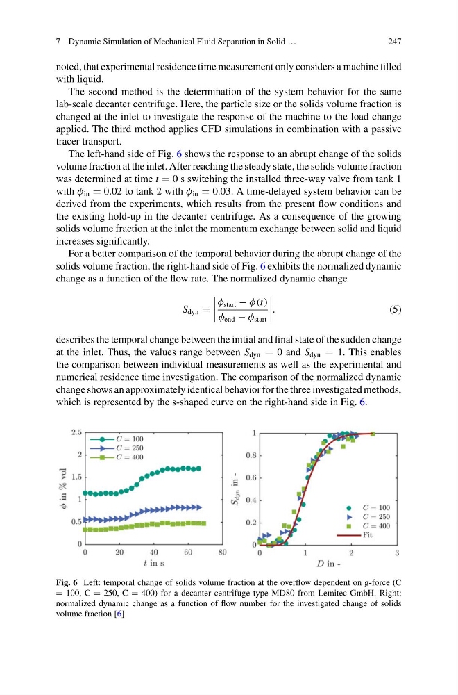
The left-hand side of Fig. 6 shows the response to an abrupt change of the solids
volume fraction at the inlet. After reaching the steady state, the solids volume fraction
was determined at time t = 0 s switching the installed three-way valve from tank 1
with φ in = 0.02 to tank 2 with φ in = 0.03. A time-delayed system behavior can be
derived from the experiments, which results from the present flow conditions and
the existing hold-up in the decanter centrifuge. As a consequence of the growing
solids volume fraction at the inlet the momentum exchange between solid and liquid
increases significantly.
For a better comparison of the temporal behavior during the abrupt change of the
solids volume fraction, the right-hand side of Fig. 6 exhibits the normalized dynamic
change as a function of the flow rate. The normalized dynamic change
S dyn =
φ start − φ(t)
φ end − φ start
.
(5)
describes the temporal change between the initial and final state of the sudden change
at the inlet. Thus, the values range between S dyn = 0 and S dyn = 1. This enables
the comparison between individual measurements as well as the experimental and
numerical residence time investigation. The comparison of the normalized dynamic
change shows an approximately identical behavior for the three investigated methods,
which is represented by the s-shaped curve on the right-hand side in Fig. 6.
Fig. 6 Left: temporal change of solids volume fraction at the overflow dependent on g-force (C
= 100, C = 250, C = 400) for a decanter centrifuge type MD80 from Lemitec GmbH. Right:
normalized dynamic change as a function of flow number for the investigated change of solids
volume fraction [6]
247
noted, that experimental residence time measurement only considers a machine filled
with liquid.
The second method is the determination of the system behavior for the same
lab-scale decanter centrifuge. Here, the particle size or the solids volume fraction is
changed at the inlet to investigate the response of the machine to the load change
applied. The third method applies CFD simulations in combination with a passive
tracer transport.
The left-hand side of Fig. 6 shows the response to an abrupt change of the solids
volume fraction at the inlet. After reaching the steady state, the solids volume fraction
was determined at time t = 0 s switching the installed three-way valve from tank 1
with φ in = 0.02 to tank 2 with φ in = 0.03. A time-delayed system behavior can be
derived from the experiments, which results from the present flow conditions and
the existing hold-up in the decanter centrifuge. As a consequence of the growing
solids volume fraction at the inlet the momentum exchange between solid and liquid
increases significantly.
For a better comparison of the temporal behavior during the abrupt change of the
solids volume fraction, the right-hand side of Fig. 6 exhibits the normalized dynamic
change as a function of the flow rate. The normalized dynamic change
S dyn =
φ start − φ(t)
φ end − φ start
.
(5)
describes the temporal change between the initial and final state of the sudden change
at the inlet. Thus, the values range between S dyn = 0 and S dyn = 1. This enables
the comparison between individual measurements as well as the experimental and
numerical residence time investigation. The comparison of the normalized dynamic
change shows an approximately identical behavior for the three investigated methods,
which is represented by the s-shaped curve on the right-hand side in Fig. 6.
Fig. 6 Left: temporal change of solids volume fraction at the overflow dependent on g-force (C
= 100, C = 250, C = 400) for a decanter centrifuge type MD80 from Lemitec GmbH. Right:
normalized dynamic change as a function of flow number for the investigated change of solids
volume fraction [6]