

6 Dynamic Process Models for Fine Grinding and Dispersing
227
40
50
60
70
80
200
400
600
800
1000
1200
1400
V = 100 L/h
v t = 8 m/s
d gb = 2.5 mm
Mixing stream R (L/h)
Media filling (%)
Normal classifier
Classifier with reduced pin number
V free,cell
V free,cell
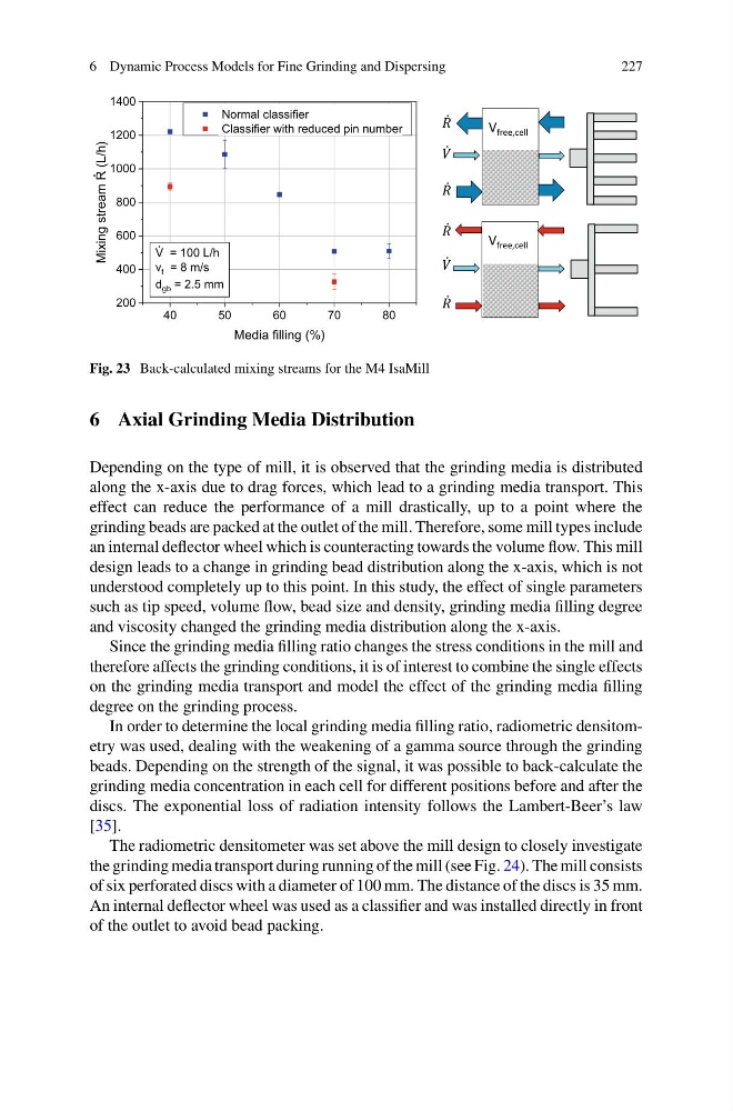
Fig. 23 Back-calculated mixing streams for the M4 IsaMill
6 Axial Grinding Media Distribution
Depending on the type of mill, it is observed that the grinding media is distributed
along the x-axis due to drag forces, which lead to a grinding media transport. This
effect can reduce the performance of a mill drastically, up to a point where the
grinding beads are packed at the outlet of the mill. Therefore, some mill types include
an internal deflector wheel which is counteracting towards the volume flow. This mill
design leads to a change in grinding bead distribution along the x-axis, which is not
understood completely up to this point. In this study, the effect of single parameters
such as tip speed, volume flow, bead size and density, grinding media filling degree
and viscosity changed the grinding media distribution along the x-axis.
Since the grinding media filling ratio changes the stress conditions in the mill and
therefore affects the grinding conditions, it is of interest to combine the single effects
on the grinding media transport and model the effect of the grinding media filling
degree on the grinding process.
In order to determine the local grinding media filling ratio, radiometric densitometry was used, dealing with the weakening of a gamma source through the grinding
beads. Depending on the strength of the signal, it was possible to back-calculate the
grinding media concentration in each cell for different positions before and after the
discs. The exponential loss of radiation intensity follows the Lambert-Beer’s law
[35].
The radiometric densitometer was set above the mill design to closely investigate
the grinding media transport during running of the mill (see Fig. 24). The mill consists
of six perforated discs with a diameter of 100 mm. The distance of the discs is 35 mm.
An internal deflector wheel was used as a classifier and was installed directly in front
of the outlet to avoid bead packing.
227
40
50
60
70
80
200
400
600
800
1000
1200
1400
V = 100 L/h
v t = 8 m/s
d gb = 2.5 mm
Mixing stream R (L/h)
Media filling (%)
Normal classifier
Classifier with reduced pin number
V free,cell
V free,cell
Fig. 23 Back-calculated mixing streams for the M4 IsaMill
6 Axial Grinding Media Distribution
Depending on the type of mill, it is observed that the grinding media is distributed
along the x-axis due to drag forces, which lead to a grinding media transport. This
effect can reduce the performance of a mill drastically, up to a point where the
grinding beads are packed at the outlet of the mill. Therefore, some mill types include
an internal deflector wheel which is counteracting towards the volume flow. This mill
design leads to a change in grinding bead distribution along the x-axis, which is not
understood completely up to this point. In this study, the effect of single parameters
such as tip speed, volume flow, bead size and density, grinding media filling degree
and viscosity changed the grinding media distribution along the x-axis.
Since the grinding media filling ratio changes the stress conditions in the mill and
therefore affects the grinding conditions, it is of interest to combine the single effects
on the grinding media transport and model the effect of the grinding media filling
degree on the grinding process.
In order to determine the local grinding media filling ratio, radiometric densitometry was used, dealing with the weakening of a gamma source through the grinding
beads. Depending on the strength of the signal, it was possible to back-calculate the
grinding media concentration in each cell for different positions before and after the
discs. The exponential loss of radiation intensity follows the Lambert-Beer’s law
[35].
The radiometric densitometer was set above the mill design to closely investigate
the grinding media transport during running of the mill (see Fig. 24). The mill consists
of six perforated discs with a diameter of 100 mm. The distance of the discs is 35 mm.
An internal deflector wheel was used as a classifier and was installed directly in front
of the outlet to avoid bead packing.