

12
S. Sander et al.
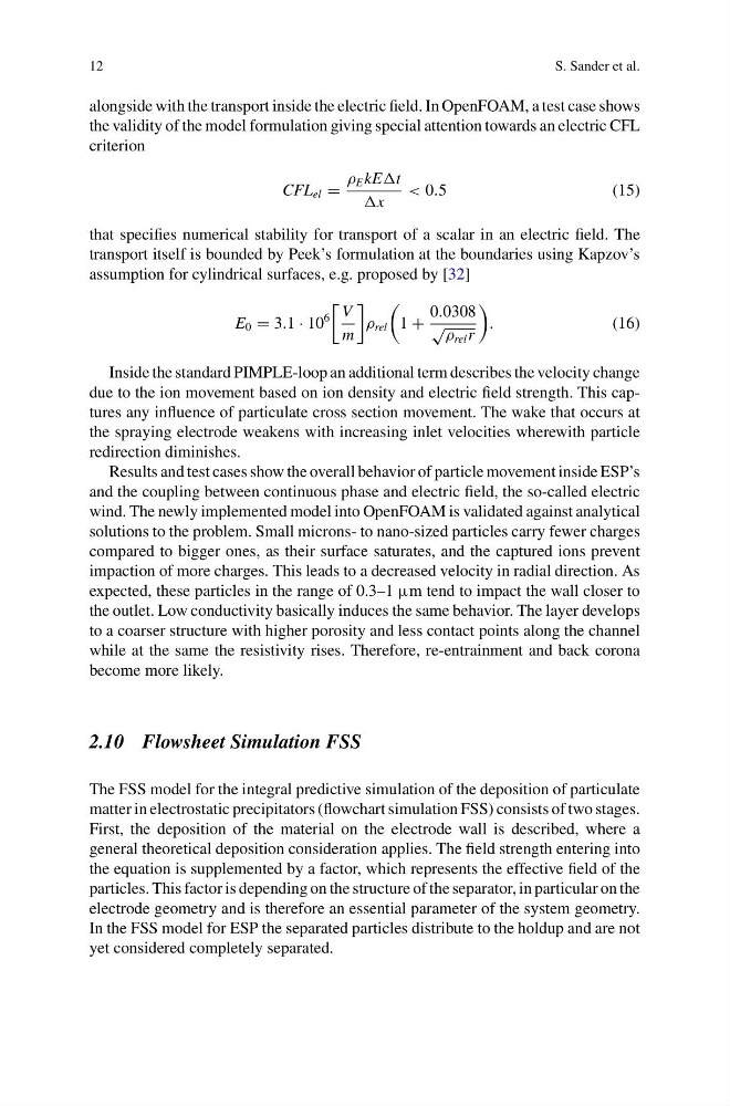
alongside with the transport inside the electric field. In OpenFOAM, a test case shows
the validity of the model formulation giving special attention towards an electric CFL
criterion
CFL el =
ρ E kEt
x
< 0.5
(15)
that specifies numerical stability for transport of a scalar in an electric field. The
transport itself is bounded by Peek’s formulation at the boundaries using Kapzov’s
assumption for cylindrical surfaces, e.g. proposed by [32]
E 0 = 3.1 · 10
6
V
m
ρ rel
1 +
0.0308
√ ρ rel r
.
(16)
Inside the standard PIMPLE-loop an additional term describes the velocity change
due to the ion movement based on ion density and electric field strength. This captures any influence of particulate cross section movement. The wake that occurs at
the spraying electrode weakens with increasing inlet velocities wherewith particle
redirection diminishes.
Results and test cases show the overall behavior of particle movement inside ESP’s
and the coupling between continuous phase and electric field, the so-called electric
wind. The newly implemented model into OpenFOAM is validated against analytical
solutions to the problem. Small microns- to nano-sized particles carry fewer charges
compared to bigger ones, as their surface saturates, and the captured ions prevent
impaction of more charges. This leads to a decreased velocity in radial direction. As
expected, these particles in the range of 0.3–1 μm tend to impact the wall closer to
the outlet. Low conductivity basically induces the same behavior. The layer develops
to a coarser structure with higher porosity and less contact points along the channel
while at the same the resistivity rises. Therefore, re-entrainment and back corona
become more likely.
2.10 Flowsheet Simulation FSS
The FSS model for the integral predictive simulation of the deposition of particulate
matter in electrostatic precipitators (flowchart simulation FSS) consists of two stages.
First, the deposition of the material on the electrode wall is described, where a
general theoretical deposition consideration applies. The field strength entering into
the equation is supplemented by a factor, which represents the effective field of the
particles. This factor is depending on the structure of the separator, in particular on the
electrode geometry and is therefore an essential parameter of the system geometry.
In the FSS model for ESP the separated particles distribute to the holdup and are not
yet considered completely separated.
S. Sander et al.
alongside with the transport inside the electric field. In OpenFOAM, a test case shows
the validity of the model formulation giving special attention towards an electric CFL
criterion
CFL el =
ρ E kEt
x
< 0.5
(15)
that specifies numerical stability for transport of a scalar in an electric field. The
transport itself is bounded by Peek’s formulation at the boundaries using Kapzov’s
assumption for cylindrical surfaces, e.g. proposed by [32]
E 0 = 3.1 · 10
6
V
m
ρ rel
1 +
0.0308
√ ρ rel r
.
(16)
Inside the standard PIMPLE-loop an additional term describes the velocity change
due to the ion movement based on ion density and electric field strength. This captures any influence of particulate cross section movement. The wake that occurs at
the spraying electrode weakens with increasing inlet velocities wherewith particle
redirection diminishes.
Results and test cases show the overall behavior of particle movement inside ESP’s
and the coupling between continuous phase and electric field, the so-called electric
wind. The newly implemented model into OpenFOAM is validated against analytical
solutions to the problem. Small microns- to nano-sized particles carry fewer charges
compared to bigger ones, as their surface saturates, and the captured ions prevent
impaction of more charges. This leads to a decreased velocity in radial direction. As
expected, these particles in the range of 0.3–1 μm tend to impact the wall closer to
the outlet. Low conductivity basically induces the same behavior. The layer develops
to a coarser structure with higher porosity and less contact points along the channel
while at the same the resistivity rises. Therefore, re-entrainment and back corona
become more likely.
2.10 Flowsheet Simulation FSS
The FSS model for the integral predictive simulation of the deposition of particulate
matter in electrostatic precipitators (flowchart simulation FSS) consists of two stages.
First, the deposition of the material on the electrode wall is described, where a
general theoretical deposition consideration applies. The field strength entering into
the equation is supplemented by a factor, which represents the effective field of the
particles. This factor is depending on the structure of the separator, in particular on the
electrode geometry and is therefore an essential parameter of the system geometry.
In the FSS model for ESP the separated particles distribute to the holdup and are not
yet considered completely separated.